|
|
|
|
|
| Author |
|
|
PCA Member since 1988
|
Details on fuel pump relay in 1978 to 1983 SC
Gents: I've searched though several past threads about SC fuel pump relays, and I think I have a pretty good understanding of them and how they are wired, so let me confirm that.
Project: I have a CIS 1980 SC engine in my CIS 1973T car. Years ago when I replaced the engine, I swapped around some of the pins in the connector between the engine harness and the circuit panel at the left rear of the engine bay to get it to work and power the gauges correctly. Several years ago I switched from an externally regulated alternator to as WOSP high-amp alternator with internal regulator. So I've had the VR, its connectors ,and other wires hanging out that didn't do anything. A few days ago I decided to clean up the wiring by eliminating most of the extra connectors and wires, and to either repurpose some of the wiring in the chassis harness or add a wire to add an oil pressure light and buzzer to my instrument panel (the 1973 cars did not have an oil pressure light or buzzer, but the later cars did have the light). I also decided to add a fuel pump relay, because the 1973 cars did not have one--they took power straight from the ignition switch. I also thought this would be a good point to add the safety cutoff function that comes from the switch on the CIS air metering unit. Fortunately, there is an extra round relay socket on the circuit panel next to the CIS relay socket (also round). That extra socket was used for the Sportomatic or MFI system on the 1973 and earlier cars, so I can repurpose it and rewire it for the a fuel pump relay. The safety switch on the airflow sensor is closed to ground when the air metering arm is at the rest position (all the way down). This prevents the pump from running when the engine is not running. It opens when the air metering arm lifts. The fuel pump runs when the pump relay is normally closed from pin 87a to pin 30. The pump stops when that ground through the safety switch is completed (closed), which occurs when the sensor arm drops to the rest position. That moves the relay contact from pin 87a to pin 87. Therefore, the pump needs to be wired "backwards" from the usual relay mode of operation (pin 87 to pin 30 for applying power to a device). Is this a correct understanding of the wiring and operation of the fuel pump relay in SC's? And I know I should get a red relay with the internal diode, but I have several black ones handy, so that's what I will use until I have it working correctly. Thanks. EDIT: I crossed up the cut and paste in my original message swhich mangled the meaning, so I have corrected that above.
__________________
1973.5 911T with RoW 1980 SC CIS stroked to 3.2, 10:1 Mahle Sport p/c's, TBC exhaust ports, M1 cams, SSI's. RSR bushings & adj spring plates, Koni Sports, 21/26mm T-bars, stock swaybars, 16x7 Fuchs w Michelin Pilot Sport A/S 3+, 205/55-16 at all 4 corners. Cars are for driving. If you want art, get something you can hang on the wall! Last edited by PeteKz; 12-13-2023 at 01:12 PM.. |
||
 12-12-2023, 01:43 PM
|
|
|
Registered
Join Date: Oct 2019
Location: Ottawa
Posts: 734
|
I like the diode in place to help protect the over-rev electronics box mostly and looks like to also protect the alarm system
 Phil
__________________
81 SC. 930/16 (us model) |
||
|
12-12-2023, 02:03 PM
|
|
|
Registered
|
Quote:
Quote:
You can easily solder/add that diode to a black relay by yourself.    Here's how it should be soldered: 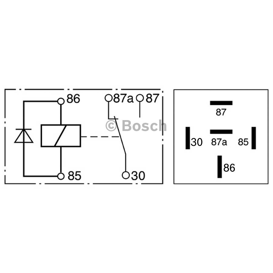 86 = 12v and 85 = GND The flyback diode in the fuel pump relay is primary used to protect the electronics in the Rev limiter switch (if existing the car) as its directly connected to the terminal 85 and 86 of the FP relay. EDIT: I See now its exactly what Phil meant
__________________
911 SC 3.0, 1982, black, US model with own digital CPU based lambda ECU build and digital MAP based ignition control All you need to know about the 930/16 and 930/07 Lamba based 911 SC US models: https://nineelevenheaven.wordpress.com/english/ Last edited by AndrewCologne; 12-24-2023 at 07:27 AM.. |
||
|
12-12-2023, 02:12 PM
|
|
|
PCA Member since 1988
|
Phil and Andrew, thanks for the quick responses. Upon further investigation, I have an additional problem. The extra socket does not have 5 pins. It only has 4. The fuel pump relay uses the 5th pin (87a) for its normally closed operation of the pump. So I have to get a socket that has 5 pins. Does anyone have a preferred source?
As for the diode, my car has no alarm, etc. So momentary voltage spikes would only hurt my tach or radio, which is a newish Sony. I doubt it would have any effect on the CDI box. certainly not any more than when I switch the ignition on and off. already But I will look for a red relay, or modify the black relay.
__________________
1973.5 911T with RoW 1980 SC CIS stroked to 3.2, 10:1 Mahle Sport p/c's, TBC exhaust ports, M1 cams, SSI's. RSR bushings & adj spring plates, Koni Sports, 21/26mm T-bars, stock swaybars, 16x7 Fuchs w Michelin Pilot Sport A/S 3+, 205/55-16 at all 4 corners. Cars are for driving. If you want art, get something you can hang on the wall! Last edited by PeteKz; 12-13-2023 at 12:45 PM.. |
||
|
12-12-2023, 02:28 PM
|
|
|
Registered
|
Pete, maybe you should take into consideration a 15v TVS diode in combination with a 47 µH Inductor to protect further sensible electronics in your circuit – a fuse like 1a (depending on the load/ampere the target device(s) draw and the inductor/TVS capacity in watts) in front of the inductor/TVS is mandatory as the TVS diode on spikes simply does a short cut where the fuse here protects the components from further damage.
A rectifier diode additionally in series with proper amp capacity could be an option as well as its a plus for preventing from negative voltage spikes, but on the other hand this reduces the voltage by approx 0.5v! https://www.mikrocontroller.net/articles/Kfz_Spannungsspitzenkiller_/_Transientenschutz I guess you can use an online translator to switch it to your language.
__________________
911 SC 3.0, 1982, black, US model with own digital CPU based lambda ECU build and digital MAP based ignition control All you need to know about the 930/16 and 930/07 Lamba based 911 SC US models: https://nineelevenheaven.wordpress.com/english/ Last edited by AndrewCologne; 12-12-2023 at 02:49 PM.. |
||
|
12-12-2023, 02:38 PM
|
|
|
Registered
|
i wonder what is inside these aluminium relays inside(my little stash);-)?Never took one apart

__________________
1985 911 with original 502 191 miles...808 198 km "The difference between genius and stupidity is that, genius has its limits". Albert Einstein. |
||
|
12-12-2023, 03:13 PM
|
|

|
|
Registered
Join Date: Jul 2003
Location: Glorious Pac NW
Posts: 4,184
|
Quote:
Dennis replied in permalink saying Quote:
Kroon make complete fuel pump harnesses for middies and/or SCs, that might also be of interest: Fuel pump harness for Porsche 911 / 911S / Carrera 3.0 1977 / 911 SC ROW 78- art.no: 911.612.072.14 Fuel pump harness for Porsche 911 SC US art.no: 911.612.072.01 No personal experience with either - but others have spoken in glowing terms of both.
__________________
'77 S with '78 930 power and a few other things. |
||
|
12-12-2023, 04:12 PM
|
|
|
Registered
Join Date: Oct 2019
Location: Ottawa
Posts: 734
|
Hi Pete,
Can't answer 4 or 5 pins, but what I was trying to say earlier is twofold. You could add the rev limiter that uses the relay. Or / if you don't attach the electronic rev limiter then it probably won't matter if you have a diode or not as there is nothing for the voltage spike to damage. Phil
__________________
81 SC. 930/16 (us model) |
||
|
12-12-2023, 05:09 PM
|
|
|
Registered
|
CIS Fuel Pump Relay Operation
..
Quote:
Peter, Sorry to disagree with your post. But your understanding how the FP relay works is FLAWED. Why? With power applied to the relay, the FP will NOT RUN as long as terminal #85 is GROUNDED (controlled by the safety switch). Your understanding how the air flow switch operates is BACKWARD. So the answer to your question is NO. Tony |
||
|
12-12-2023, 08:06 PM
|
|
|
PCA Member since 1988
|
Spuggy, thanks for the reference to timmy2.
I was thinking about this as I was laying in bed last night (hey, Porsche wiring diagrams are better than counting sheep), and upon further reflection, I think I can split open the hole where the 5th socket should go, and insert a socket and wire in there. If I cut down from the top of the socket, then when I stuff the whole plug back into the circuit board, the metal board will hold it together effectively. That way, I don't have to wait for one to arrive. In cutting and pasting the text to edit my original message, I made a mistake and mangled it. I have corrected that in the original message. For completeness in this thread, here is the section of the SC wiring diagram that shows the fuel pump relay and pump circuit. 
__________________
1973.5 911T with RoW 1980 SC CIS stroked to 3.2, 10:1 Mahle Sport p/c's, TBC exhaust ports, M1 cams, SSI's. RSR bushings & adj spring plates, Koni Sports, 21/26mm T-bars, stock swaybars, 16x7 Fuchs w Michelin Pilot Sport A/S 3+, 205/55-16 at all 4 corners. Cars are for driving. If you want art, get something you can hang on the wall! |
||
|
12-13-2023, 12:57 PM
|
|
|
Still here
|
Quote:
|
||
|
12-13-2023, 01:58 PM
|
|
|
Registered

|
Quote:
https://nineelevenheaven.wordpress.com/the-protection-circuit-of-the-fuel-pump/ Browse all states by clicking on the arrows left and right of the circuit picture...then it should be pretty clear how it works. Thomas
__________________
1981 911 SC Coupé, platinum met. (former tin (zinc) metallic), Bilstein shocks, 915/61,930/16,WebCam20/21, Dansk 92.502SD,123ignition distributor with Permatune box as amplifier,Seine Systems Gate Shift Kit,Momo Prototipo. Want to get in touch with former owners of the car. Last registration in US was in 2013 in Lincolnshire/lL. |
||
|
12-14-2023, 10:26 AM
|
|
|
PCA Member since 1988
|
Thomas, thanks for the reference. I did look at Andrew's web site too. I understand how the relay works. The interesting task is adapting it to the wiring in my 1973 car with the minimum of electrical surgery.
By the way, my car has a brown/white stripe wire that goes from the Auxiliary Starting Relay connector, on the engine bay circuit panel (for cars with MFI), to the chassis wiring loom. That relay was not installed in my 1973.5T because it had CIS originally, but the connector and wiring was built into the harness. I do not see it on the several wiring diagrams I have consulted. Does anyone know where the other end of this wire comes out of the chassis wire harness?
__________________
1973.5 911T with RoW 1980 SC CIS stroked to 3.2, 10:1 Mahle Sport p/c's, TBC exhaust ports, M1 cams, SSI's. RSR bushings & adj spring plates, Koni Sports, 21/26mm T-bars, stock swaybars, 16x7 Fuchs w Michelin Pilot Sport A/S 3+, 205/55-16 at all 4 corners. Cars are for driving. If you want art, get something you can hang on the wall! |
||
|
12-14-2023, 03:33 PM
|
|
|
Registered
|
Quote:
Even I do not recommend the follwoing, ... but you also could do it the classic common way and use the oil pressure lamp signal to drive your FP protection circuit, there are several approaches shown in the web.
__________________
911 SC 3.0, 1982, black, US model with own digital CPU based lambda ECU build and digital MAP based ignition control All you need to know about the 930/16 and 930/07 Lamba based 911 SC US models: https://nineelevenheaven.wordpress.com/english/ |
||
|
12-15-2023, 04:45 AM
|
|
|
Registered
|
Quote:
I use it for idle set up instead of the wire clip....;-)  
__________________
1985 911 with original 502 191 miles...808 198 km "The difference between genius and stupidity is that, genius has its limits". Albert Einstein. |
||
|
12-15-2023, 07:05 AM
|
|
|
Registered
|
Basic design premise of electrical safety circuits is to use "negative logic".
Switch the ground instead of the power which might not be available in all cases after an incident.
__________________
1980 911 - Metzger 3.6L 2016 Cayman S |
||
|
12-15-2023, 07:53 AM
|
|
|
Registered
|
since we are talking relay ..i have forgotten what is this one for? if i remember it was on 1970-73?
Ivan   
__________________
1985 911 with original 502 191 miles...808 198 km "The difference between genius and stupidity is that, genius has its limits". Albert Einstein. |
||
|
12-15-2023, 07:56 AM
|
|
|
Registered
|
5-Pin Round Relay
.
Ivan,
The relay has the same 5-pin configuration as the RED RELAY for FP except for the colored pins. It should work for switching terminals #87A & #87 as the Red Relay. Have you decided to come back to US? Thanks. Tony |
||
|
12-15-2023, 10:04 AM
|
|

|
|
Registered
|
Quote:
__________________
1985 911 with original 502 191 miles...808 198 km "The difference between genius and stupidity is that, genius has its limits". Albert Einstein. Last edited by proporsche; 12-15-2023 at 11:12 AM.. |
||
|
12-15-2023, 11:10 AM
|
|


 Volkswagen Bug - Split window
 Porsche 911
 Volkswagen Bug - Oval window
 Black Label
 Porsche 911 SC
