|
|
|
|
|
| Author |
|
|
Registered
Join Date: May 2008
Posts: 47
|
'81 CIS ECU wiring question
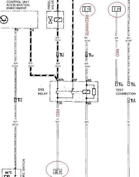 So I was looking in the big shop manual trying to figure out how to help Rick911S hook up his CIS computer (1981) to the power source on his 1976 targa chassis. I just want to help confirm what I think I'm seeing on the diagrams. We do not want to blow anything up! Page 842 of the manual shows what appear to be 3 power wires. There doesn't seem to be a key to show what the roman numeral symbols (ex: "III 9") mean. I looked at another diagram and here is what it seemed to show. 1. "III 9" corresponds to "Fuse 16." 2. "I 13" corresponds to "Warm-up Regulator" (I don't fully understand that) 3. "I 21" seems to be "Fuse 22" Page 832 shows that Fuses 16 and 22 both go to pin 25A, which is fuse position for the fuel pump. Is that correct? Finally, it looks like "I 13," the red and white line that goes to the WUR, is also marked "T1d" which seems to mean it goes to a one-pin connector behind the fuse panel. Another diagram seemed to show it going into the big 14-pin connector on the regulator panel. I'm confused! Or if anyone has a simpler (ie, idiot-proof) way of explaining this to me, that would be great! Last edited by felixcontour; 02-02-2009 at 03:50 PM.. |
||
 02-02-2009, 03:29 PM
|
|
|
Registered
Join Date: May 2008
Posts: 47
|
I think I made this more complicated than it needs to be. How about I ask it this way?
Would it be ok to: 1. run the two power wires from the relay up to the fuel pump fuse? 2. run the diagnostic port power wire to a fuse in the engine bay? (and which one?) OK, that is MUCH simpler. |
||
|
02-02-2009, 04:29 PM
|
|
|
Registered
|
Electrical wiring diagram..........
Quote:
Refering to the factory wiring diagrams (part I, II, III, IV, V, & VI), here are some answers to your inquiries: 1. III-9...........this wire (red) goes to fuse #18 (5 A) not #16. 2. I-13...........this wire (red/white) goes to T1d (connected to #30 of the FP relay). WUR & AAR are also connected to T1d. 3. I-21...........goes to fuse #22 (25 A). Now to answer your question about I-13 / T1d............at 14-pin connector: The FP relay is mounted on the chassis while the WUR & AAR are mounted on the motor or engine, and when you removed the engine from the car, the common connector is the #10 pin (14-pin connector). I'm als in the middle of a project (SC engine into a '77S system) so we will be doing similar work. BTW, there is also a very good reference wiring schematics in the Bentley SC manual (page 970-8) and much easier to follow than the factory ones. HTH. Tony |
||
|
02-02-2009, 05:41 PM
|
|
|
Registered
Join Date: May 2008
Posts: 47
|
Thanks Tony! I get the impression a Bentley manual would help a lot. I've got one coming next week, so I'll take a look at the diagrams with what you said in mind.
|
||
|
02-02-2009, 07:01 PM
|
|


