|
|
|
|
|
| Author |
|
|
Registered User
|
CIS wiring - advice, please
Hi,
Over the last couple of years I have enjoyed the wealth of information and advice found in this forum. But experiencing a very specific problem now, means that I will have to appeal to all the knowledge for more specific information.  Last year I entrusted a local B***H Service Center with the task of curing a hot starting problem with my 1976 911S 2,7. 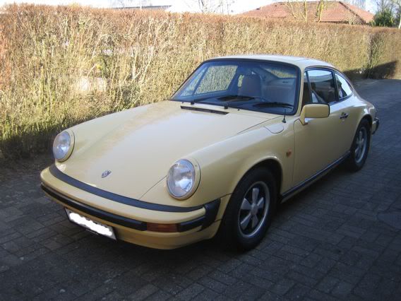 They used 3 attempts and billed me for more than 25 hours installing a brand new Air Flow Meter, a new Cold Start Valve and replacing part of the wiring loom connecting the injection system. Apart from costing a fortune, it only rendered the car undrivable, as their work had apparently created a new problem that caused the revs to surge violently. The shops suggestion to solving the problem was to have the Warm Up Regulator replaced with a brand new item, so I put a stop to the show and took the car home. I myself had NO idea of how a K-jet/CIS system worked, but just after a few searches on the internet, it was clear that there had to be a vacuum leak somewhere in the system. After overcoming some health issues over the winter, I finally took a dose of brave-pills and pulled the engine a couple of weeks ago. I DO believe that I have found the reason for the rev surging; 5 minutes into dismanteling the injection system, I had come across a serious vacuum leak. It turned out that the boot between the Air Flow Meter and the throttlebody was cracked halfway around the lip where it attaches to the Air Flow Meter. That hasnt exactly done wonders for my trust in the mechanics who worked on the car last year, so as I now have access to most things on the engine, I decided to check out what they had done when replacing wires in the wiring loom. I am not exactly an ace, when it comes to auto electrics and huge diagrams, but I tried to check the loom using a dummy diagram found here on Pelican: 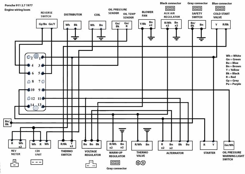 I believe that the major difference between the diagram and my 1976 car is that my car does not have the Thermo Valve? It was fairly obvious which wires had been changed, as it was all made with "nice" new white and blue wires The majority of connections in the loom checks out fine with the diagram, but I am NOT sure about the new additions to the loom. The connections to the Warm Up Regulator and the Cold Start Valve looks a bit strange to me. I have tried to make a modified diagram to show the new connections as they are on the car now: 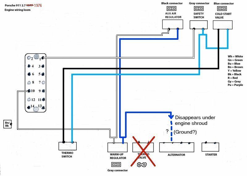 Provided that the mysterious blue wire disappearing beneath the engine shroud is to a ground terminal on the alternator, I suppose the Warm Up Regulator should be constantly energized while the engine is running. I suppose that would be OK? I am somewhat more puzzled about what is going on with the Cold Start Valve. As I understand it, the CSV should get power, when the starter is activated, and the temperature is low enough to activate the Thermo Switch? First of all, they have wired it through the Safety Switch (Air Flow Meter). This must mean, that the connection to Terminal 1 will break as soon as the AFM starts taking air in? Does that sound as a good idea? Secondly I cant figure out where the CSV gets its ground connection. To me it looks like the connection between the Thermo Switch and the CSV just forms a dead circuit??? or am I completely wrong? Any suggestions/comments, please... /HenrikH |
||
 05-11-2013, 04:44 AM
|
|
 |
|
|
| Tags |
| cis , k-jetronic , wiring engine bay |


 911S
911S

