 |
 |
 |
 |

|

|
|
|
|
|
|
Registered
|
I understand that when running the gauge in CLOSED LOOP MODE, utilizing the O2 sensor, you set the gauge to position #4.
What position will you set the gauge in an OPEN LOOP MODE, without the O2 sensor? |
||
|
|
|
|
Registered
|
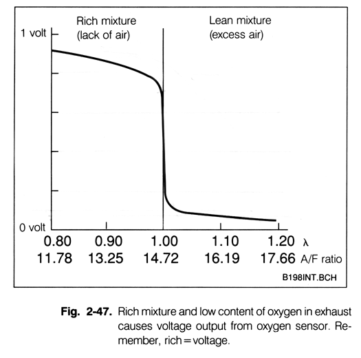
Not entirely sure what you are getting at. The positions dictate what voltage output comes across the analog output wire. P4 emulates a narrow band sensor with a voltage output of 0-1V.
|
||
|
|
|
|
Registered
|
Aem 30-4110 gauge
I performing tests that require to have the AFR values read on a stock, non o2 sensor configuration. #1 - 0-5v, #2 - 1-2v #3 0-1v #4 - 0-1v non linear
AEM support said that I can leave it at #4. do you agree? |
||
|
|
|
|
Registered
|
What do you have the analog output wire connected to?
|
||
|
|
|
|
Registered
|
to the DME
|
||
|
|
|
|
Registered
|
The DME will always have that signal present, even in the factory configuration. The DME determines when to look at or ignore that signal (Open and Closed loop). There is nothing that needs to be changed on the gauge end with respect to open and closed loop.
|
||
|
|
|

|
|
Registered
|
You will need the gauge to emulate this signal:
 According to AEM's documentation, mode P4 emulates that signal: 
|
||
|
|
|