Well I did find my stash of mirror wiring info - but it may not apply since it's all US spec and you're down-under and on the "wrong" side. Hopefully there are some similarities......
It would help if you could send a photo of your pass. side mirror and connector. Are you sure about the 7 pin DIN? Everything I have here (and the factory manual) is based on a
six pin connector.
Also, I'm curious that you say the cable is missing. Was this mirror added at some time? As you may know, it's hard to take a flag mirror completely off without cutting the cable. This often happens when mirrors are painted or replaced. Have you checked inside your door? If the cut end of the cable is there (coming through the door jamb) then you probably have factory wiring set up. If there's no cable running between the trunk and the door, the car did not originally have a pass side mirror and yours was added later. This is the case with my '77. Most of the US cars only had one mirror. I added a pass mirror but have not yet run a cable - so it's manual just like yours.
Another confusion factor is to figure out which type of mirrors you have. '77 cars here had the older type - call it Type A - which has one motor and a magnetic clutch inside. Newer types look the same but have two separate motors. If you mix and match types, you can't use a single joystick switch - they are not compatible. In my setup, I ended up getting a newer Type B mirror for the pass side and I will need to add a second joysitck switch. The factory designs allow you to use the single control switch in your drivers door and you select the left or right mirror with a switch under the speedometer.
Anyway, since we are dealing with a time lag, I'm sending info on both types. Feel free to filter this out and send me more details and questions.
Here are photos of both types:

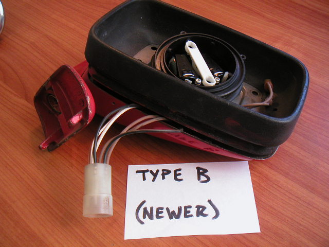
And here are the associated connectors - again, both are 6 Pin

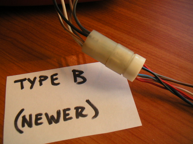
Here's the pin out info based on the parts I have. (Numbers are molded into the ends of the connectors. I don't know if the columns will line up when I post this so here is the format for the info below)
Pin Number - Wire Color From Mirror To Connector - Wire Color From Connector to Chassis Harness - Function.
Type A
Pin 1 - Blue - Blue - Motor Lead (a)
Pin 2 - Black - Black/Yellow - Motor Lead (b)
Pin 3 - Gray/Green - Gray/Green - Heater (a)
Pin 4 - Brown - Brown - Heater (b)
Pin 5 - Brown - Brown - Magnetic Clutch (a)
Pin 6 - White - White - Magnetic Clutch (b)
Type B
Pin 1 - White - Two Wires: Red and White/Red - Motor Common*
Pin 2 - White/Brown - Blue/Gray - Left/Right Operating Lead
Pin 3 - Black - Black/Blue - Up/Down Operating Lead
Pin 4 - Black/Brown - Red - Motor Common*
Pin 5 - Brown - Gray/Green - Heater (a)
Pin 6 - Brown - Brown - Heater (b)
* Note: The Red wire on Pins 1 and 4 is the same wire. It loops from 1 to 4 on the back of the chassis connector.
I hope this helps. I can try to send the factory wiring diagram (Type A only) if needed.
Ron