|
|
|
|
|
| Author |
|
|
Registered
Join Date: May 2004
Location: Boulder, Colorado
Posts: 7,275
|
Measuring valve lift
Question: What angles do the air cooled 911 intake and exhaust valves, through at least the 3.2s, have to the plane of the valve cover mating surfaces? These are at 30 degrees to the cylinder top/head surfaces (at least if the 120 degree angle between the intake and exhaust valve covers means the angle to the cam carrier mounting surface is divided equally at 30 degrees per side).
Longish reason I am interested: As a hobby within a hobby, I look for ways to detect performance enhancements which are contrary to certain racing rules for the model and class. I'm working on an elaborate system, using a microcomputer, coded outputs from digital "dial" indicators, and a rotary encoder. The result will be what amounts to an in-car or assembled engine cam doctor. Someday (rotation speed vs. data transfer speeds add complication). The exhaust cam can be measured directly on the lobe. To avoid having to remove an intake rocker to access that lobe, I've switched to measuring intake valve lift. I revised setup 2:  so the one holder could hold both indicators: 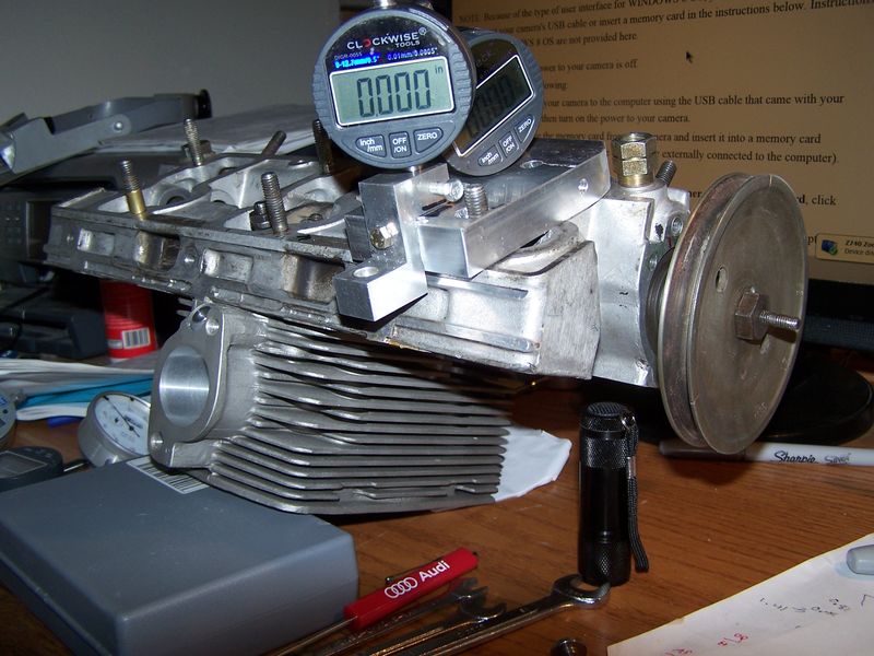 This can be used to measure just maximum lift. No automation involved here, just watch the numbers as the crank turns the cam. Testing on the bench and in my SC verifies that the maximum exhaust lobe lift is within a thousandth of an inch of the measured lobe. So the jig has the axis of the indicator on a radius of the cam axis. So far, so good. The specs one usually finds give intake valve lift for an SC and 3.2 cam of 0.450". When measuring this using the standard Z block we all use to set cam timing, the results were uniformly well below this figure, the best being 0.447" (which might be good enough) and 0.435", which couldn't be right. Switching between 0.004" lash and 0 lash produced inconsistent results. Why is that? I used a temporary setup to see if the 0.450" figure was correct:  Given that getting the indicator coaxial with the valve stem was done by eyeball, getting 0.449" as a result persuaded me that the cam was performing to specification. So why the problem measuring intake lift from the valve spring retainer? It has only a rather narrow flat annular ring on which to get accurate measurements, but the indicator tip was on this. But when I measured the depth below the cam carrier/valve cover surface down to the retainer at the cam side and the intake manifold side, the measurements were different. Not necessarily quantitatively accurate, but qualitatively accurate. This indicated to me that the angle of the valve stem is not perpendicular to the valve cover surface, which is where we mount our Z blocks. Reaching back to high school trig, and my experience as a prosecutor of speeders busted with police traffic radar, I realized (or perhaps should say I suspected) that I was looking at the cosine effect. In a measurement like this, if the measuring device is not moving on the same axis (or at least coaxially) with the object, the measurement shown will be short by the cosine of the angle off. Which explains the discrepancy. And suggests the variability comes from small differences in either the angle of the Z block (though the mounting surface is uniform) or perhaps where, on a 360 degree circle, on the retainer the tip of the indicator is. None of this matters when setting cams - the lifts are too small to be affected, and a few thousandths of an inch are well within the cam timing tolerances and any reasonable expectation of side to side tolerance. But it seems to come into play when checking maximum valve lift with a Z block or otherwise from the topside. From a compliance perspective, this is fine - as with radar, the cosine discrepancy from true is in favor of what is being checked (unless you are setting land speed records or at the drags, I suppose). |
||
 08-21-2019, 08:27 PM
|
|
|
abit off center
|
With your numbers what is the calculated exact rocker ratio?
__________________
______________________ Craig G2Performance Twinplug, head work, case savers, rockers arms, etc. |
||
|
08-22-2019, 04:24 AM
|
|
|
Registered
Join Date: Mar 2019
Posts: 1,642
|
I have a flow bench and run into the same issue when measuring lift on the bench. Bottom line is that Porsche varied the included angles depending on the head. If you want an exact figure for the 3.2 heads, I'll measure one for you.
|
||
|
08-22-2019, 04:38 AM
|
|
|
Registered
Join Date: Mar 2004
Location: So. Ca.
Posts: 521
|
If I remember correctly the 2.7 angles were 27 intake and 32 exhaust and the 3.0 stuff was 25/30.15 respectively. Rocker ratio is constantly changing due to the radius commonly used is 1.42 on the adjustable rocker 1.45 on the non adj. racing.
regards |
||
|
08-22-2019, 08:48 AM
|
|
|
Registered
Join Date: May 2004
Posts: 891
|
I think I understand what you are trying to do, but I think you need to differentiate between designed dimensions and on engine dimensions. A big difference. In the end, the engine new or used will see what the parts included have for machined tolerances.
A couple of things to point out. Measuring cams in a cam housing will have a certain amount of error. Even when measured on typical test equipment the cam is measured between V blocks and the journals are used to support the cam. Cams are ground between centers and any accurate measuring should be done by holding them between centers. You should also have the S96 files or a master to compare against. Most cam measuring software will give the camshaft runout and will show the differences between lobes. I guess any differences will show up in your set but how accurate, you would have to compare against the S96 file. As for valve angles, again you are dealing with machining tolerances. Measuring with a valve you need to take into consideration, guide wear, stem wear, and if replaced, how well the guides were installed, and pin fitted. You may find every guide is different. It may be better to remove the guides and use the guide bores as your base line. Most camshafts sold or reground in the aftermarket will have some run out and lobe differences. Rocker arms will have as well. Many when repaired are reground without any consideration to the final ratio. Clearances between the shaft and the rocker bore will also add in some error value. Valve length will some error as well. If the rocker radius has been reground and the valves tipped, are they all the same? This will change the ratio in the engine. Using a designed number here will add into the error margins you may see. What you are doing is Ok as the engine will see and include all the errors that your heads, cam decks etc have. If this is for some in car measuring, I expect the valve train will be completely assembled with spring pressures pushing against any clearances. This could make the error margins higher but, in the end, it is what the engine sees. I think you must accept some margin of error here as every engine will be different. Maybe this is why many governing bodies seal engines at the track, then turn at the door of the engine builder and measure the components. |
||
|
08-22-2019, 09:49 AM
|
|
|
Registered
Join Date: Mar 2019
Posts: 1,642
|
Measure the lobe lift on the cam lobes and compare those to the valve lifts to get the actual rocker arm ratio. I'd bet that much of the difference is in the rocker arms. If you're chasing every last bit of power (if limited to a "stock camshaft"), it would be wise to procure as many rocker arms as possible and weed out the lower lift/ratio ones, or at least find 12 that are as closely matched as possible.
|
||
|
08-22-2019, 10:10 AM
|
|

|
|
Registered
Join Date: May 2004
Location: Boulder, Colorado
Posts: 7,275
|
Craig: The SC/3.2 cam lobes measured at 0.305" intake, 0.271 exhaust. I measured the exhaust at 0.272, but that could easily be my technique.
The published valve lift figures are 0.450/0.395. Given my measurement, I think that 0.450 is correct, at least within 0.001". That would make the rocker ratio 1.475 intake, 1.458 exhaust using the published lift figures. I haven't checked the exhaust with a Z block or on the valve head, and I don't know exactly why the same rockers would produce a different ratio for the exhaust, but perhaps it is due to the different exhaust valve angle compared with the intake. And that would only be the ratio at max lift. It is obvious that the effective lengths of the two parts of the rocker as a lever change. I suspect these variations are not all that important for engine building purposes - a guy would clay and otherwise measure for clearances, and use flow bench figures as part of your cam choice procedure. My purposes are a bit limited. Dan - It looks like guys like me who have their rockers refaced, and have lived with somewhat worn rocker bushings and shafts, are losing a bit of lift. I recall the racing rockers with shim caps to set the lash, though I am trying to think of how that substituted for the nicely accommodating elephant foot, which those didn't have, did they? I would be interested in the 3.2 head valve angles, though. Can't have too much knowledge. Neil - I for sure accept some margin of error. I'm not setting up a machine, or building a super engine. I am checking guys' race motors to see if anyone succumbed to the temptation to put a 964 cam in a 3.0 or 3.2. The lobe figure for the exhaust is accurate enough, and the 964 exhaust lift is higher enough that it is beyond any margin of error. The intake should stand out as well. The variations are all going to be toward recording less than actual lift, which is good from an enforcement standpoint. You don't want false positives. Professional race organizations (money and sponsorship on the line, etc)can demand sealed engines. Porsche will do that for their race engines in those series. Other organizations can tell the team to tear the engine down right there after the race, etc. But where many of the drivers trailered to the track themselves, have to get back to work Monday morning, and in many cases might not be able to R&R an engine anyway - a shop at home does that - other methods must be used to check on parts compliance. Besides, it is a challenge to try to figure out those methods. |
||
|
08-22-2019, 11:03 PM
|
|
|
Registered
Join Date: Mar 2019
Posts: 1,642
|
A quick note regarding "sealed" engines." In some classes nascar required sealed engines. One of my teammates went through the trouble of carefully machining down two 3/8" bolts used to seal the engine (crossdrilled for safety wire) to 5/16". He then put these two bolts on the center intake bolts of one of our race motors (SB Chevy) and put nuts on the backside of the bolts from underneath the valve cover. Nascar did their bubble and whistler checks on it, then happily "sealed" the engine. Fast forward to later in the season and we broke a cam and were forced to pop the heads and replace some bent valves after practice. Finished it up just before green flag drop, rolled it through tech, and one of the officials asked if we needed to reseal it (do the whole check procedure over again). We just hastily said, "No, it's still sealed," and pointed at the lead seals. In the heat of the moment, with other cars in line at the scale, this official just waved us through and continued on.
Bottom line is that racers are some crafty people. Seals aren't infallible. |
||
|
08-23-2019, 04:40 AM
|
|
|
Registered
Join Date: May 2004
Location: Boulder, Colorado
Posts: 7,275
|
Dan - I know what the Whistler is, but what is the bubble test? Is that where you pump the engine for displacement?
|
||
|
08-23-2019, 12:29 PM
|
|
|
Under the radar
Join Date: May 2007
Location: Fortuna, CA. On the Lost Coast near the Emerald Triangle
Posts: 7,129
|
Have you compared the right cam with the left cam? I wonder if there is a difference due to the fact that the cams are turning in opposite directions compared to the valves.
__________________
Gordon ___________________________________ '71 911 Coupe 3,0L outlawed #56 PCA Redwood Region, GGR, NASA, Speed SF Trackrash's Garage :: My Garage |
||
|
08-23-2019, 12:41 PM
|
|
|
Registered
Join Date: Mar 2019
Posts: 1,642
|
The bubble test is a big plexiglass cylinder with a plastic piston in it and a calibrated scale on the outside. At one end is an o-ring that is reset each time the displacement is measured. At the other end is a tube that screws into the spark plug hole. The rocker arms and spark plug are removed and the adapter is screwed into the spark plug hole. The engine is then cranked over with the starter and the piston moves up and down in the plexiglass cylinder. The o-ring then moves up inside the bore, stopping at a high spot. After a predetermined number of "puffs," the number on the scale is read and multiplied by the number of cylinders to determine displacement. That displacement number is then used with the electronic whistler to give them the compression ratio.
As for accuracy, it's reasonably accurate. If the blowby is high in that particular cylinder, it'll read as a smaller displacement. If you have gas ported pistons with only a top ring, it'll read "smaller" too. A low battery can also fool it, along with a couple of other more "crafty" methods, like coaxing the officials into always only testing one bank or only the front 4 cylinders, then cheating on the other cylinders. Roll cage bars or other restrictive devices purposely put in place to hinder access usually helps sway the officials to check the "easy" cylinders. https://www.speedwaymotors.com/Speedway-Engine-Cubic-Inch-Tester-Tool,703.html |
||
|
08-23-2019, 04:54 PM
|
|
|
Registered
Join Date: May 2004
Location: Boulder, Colorado
Posts: 7,275
|
Got it - I know the bubble as "pumping the engine." Pretty decent, but calls for taking off an intake and exhaust rocker for the air cooled motors, which very much limits its practicality. Not a big deal for an OHV V8, and at NASCAR levels you can just demand the heads be removed, etc. I hadn't known about the things like gas ported rings, and doubted at the PCA level the more crafty approaches would be employed - I'm discounting anyone making the #1 and 4 cam lobes to spec, and hot rodding the others. Not that much meat on the table just to keep up with your friends.
Gordon - I can think of no reason at all why there would be a right vs left cam measurement difference, outside of random small wear/tolerance differences lobe by lobe. The lobes are physically closer at max lift on the right cam (in fact, the physical lobe center is nearly at the same place on the 3.0/3.2 cams). But all that comes out in the wash as far as each cylinder is concerned. The housings are the same casting, and "reversible." Each rotates CCW. Valve stem angles the same. But I'm open to theories. At the moment, I'm so muddled I can't work out why the cam lobe physical separations are different right and left side. A guy doesn't need to know this to assemble and time his engine, just know which cam is right and which is left. |
||
|
08-24-2019, 05:04 PM
|
|

|
|
Under the radar
Join Date: May 2007
Location: Fortuna, CA. On the Lost Coast near the Emerald Triangle
Posts: 7,129
|
Walt. My point is that the cam rides against the rocker from the opposite direction on each side of the motor. Just a thought that it may make a difference. Perhaps the cam grinders have taken it in to account?
__________________
Gordon ___________________________________ '71 911 Coupe 3,0L outlawed #56 PCA Redwood Region, GGR, NASA, Speed SF Trackrash's Garage :: My Garage |
||
|
08-24-2019, 07:22 PM
|
|
|
Registered

Join Date: Oct 2005
Location: Idaho
Posts: 2,357
|
Walt,
I'm curious if you ever figured this out... and if it's a proprietary process. Reason I'm asking is I purchased a SPEC 911 race car last year with a 3.2L engine. I'd like to verify that the cams inside are stock w/out major disassembly. I'm assuming this is what you were trying to accomplish? I recently read about some 911 CUP cars that were busted for illegal cams at the 2020 Sebring Club Race. Major kudos to whoever's doing the checking in my opinion (maybe it's you?). I'd like to verify my own engine to be sure everything's as it was represented. Not that it'll make any difference if it's not as I'm pretty slow regardless! Thanks, Tom
__________________
'74 911 Red Sunroof Coupe, 3.6L, etc... '76 912 Yellow SPEC 911/911CUP |
||
|
02-25-2020, 04:51 PM
|
|
|
Registered
Join Date: May 2004
Location: Boulder, Colorado
Posts: 7,275
|
Tom
The Mark I version of the in car cam tester is nothing fancy at all. Intake lift is measured at the valve, the same way you set cams basically, but I am using the Stomski tool instead of a Z block. I had planned to measure intake on the cam lobe, but that pretty much requires pulling a rocker, so with the counsel of my colleagues decided to use the valve. Exhaust lift is measured on the cam lobe itself - most of that lobe is exposed when the intake valve cover is off. To do this I made a special holder for the dial indicator, so that it is on a plane perpendicular to the cam's axis, and is on a radius. The lobe specs for the SC/3.2 cam are 0.305" for the intake, and 0.271" for the exhaust. The published valve lift specs are 0.450" intake, and 0.395" exhaust. Quite a few cams have been measured. No stock SC/3.2 cam's intake valve lift has exceeded 0.450" when measured. In fact, all are less than that. Might have to do with valve lash, which I have tested for. Anderson gives a slightly different figure, but testing does not bear that out. The exhaust lobe measurement may be 0.372" (putting a mic on a lobe can be tricky, and when I measure my test cam I usually get the 0.372 figure. Any cam measured over these specs is not a stock 3.0/3.2 cam. It could be a sloppy regrind, though the likely suspect is a 964 cam. Cams on a well maintained engine of this type last nearly forever and shouldn't ordinarily need to be replaced or reground. Intake valve lift for a 964 is 0.470", and exhaust lobe lift is 0.287". The bad cams we measured were more than the stock figures, but a bit less than these 964 figures, especially for intake - which is consistent with testing. Cams don't magically grow, and there are no false positives with this kind of measurement. A holder for the exhaust cam lobe indicator has the hole emerging from the bottom of the holder (at the plane of the valve cover) at a 67 degree angle, centered 15mm below the center of the stud, and 0.475" in. It has to be relieved for the intake rocker and for the two nuts (barrel or hex) and 8mm studs from the head. I figured that out when I went to use it on my SC rather than just on the test setup on my desk. It is pretty easy to see the space the indicator has to fit through. The picture below shows it before I figured this out. I suspect that clever use of an adjustable indicator holder would allow you to eyeball this and get readings which are accurate enough without machining a special holder. Here's the bench test setup. The wires and extra stuff are for the Mark II version, which will use the distributor to turn a rotary indicator to allow measuring duration and lobe shape to catch cams cleverly made to have stock lift (and maybe stock duration), but steeper flanks for more area under the curve.   So it is still a work in progress - but just doing these simple measurements is progress of a sort. I hate it when we find something like the wrong cam, but for everyone's sake we've got to keep looking. If there is some good news about some of this checking of mechanical parts, it is that of around 100 Spec Boxsters checked, only a couple have been found with the wrong gears. And those were due to unknowingly ending up with the box from a later model from the junk yard, with taller gearing which hindered performance. Having a short 5th has to be a temptation in that class, but no one has succumbed that I have found. The 944 guys all have the right gears these days, too. The one 944 box which was off was clearly unknown to the driver/owner and not due to anyone trying to get an advantage. Hats off to them and their shops. Mano a mano is really what racing for fun is all about. Walt |
||
|
02-27-2020, 11:54 AM
|
|
|
Registered
Join Date: Oct 2005
Location: Idaho
Posts: 2,357
|
Hi Walt,
Thank you very much for the procedural info and specs to look for. I do have a Stomski cam timing fixture which I used this afternoon to see if I could verify the cams in 2 separate engines. Not having done this before, I feel like the results were a little inconsistent... but maybe they are in line with your experience? First, to verify my method - I set up the Stomski tool as one would do when setting cam timing, with the tip of the dial indicator sitting on the intake valve and the dial indicator zeroed when the rocker is on the backside of the cam. The number I recorded for each cylinder is the highest negative value shown on the indicator, when I suppose represents how far the valve opened. I wasn't able to measure the exhaust valves as I don't have a fixture for that. As I mentioned earlier, I was surprised at the variation between cylinders. The first engine I tested is a 2.7L engine that I am rebuilding (for the street, not race) which has cams that were allegedly reground to 964 specs. I say allegedly because the measurements I recorded were pretty far off the specs. you posted in your last post. I measured all 6 intake valves and recorded #1 - 0.406" #2 - 0.401" #3 - 0.403" #4 - 0.4025 #5 - 0.404 #6 - 0.3995 All of these numbers are well below the 0.470" spec you posted for 964 cams... so maybe my cams were not reground to 964 specs...? or are the measurements different due to the engine being a 2.7L vs. a 3.0L or 3.2L? Here's a few photos (#1 & #4) for reference...   The next engine I tested was the 3.2L engine that's in my SPEC 911 - so the cams should be stock 3.2L cams with the spec of 0.450" for the intake valve lift. On this engine I only tested the right side cylinders (as dinner time was fast approaching)... : ) : ) I recorded... #4 - 0.451" #5 - 0.4495" #6 - 0.4455" The spec you posted for the 3.2L cam was 0.450" and these measurements seem a lot more consistent than the 2.7L engine. So I guess the first thing I'd like to ask is - is my methodology correct? and are the measurements I've recording consistent with what you've seen in your experience? You mentioned that ALL measurements you've taken (of presumably stock cams) have been UNDER the published spec. - Would the 0.451" measurement I found for the #4 lobe concern you? or is it w/in acceptable tolerances? I plan to measure the left side for more data... Am I on the right track? Thanks for the discussion & help! Tom Here's some photos of the 3.2L engine - right side only...   
__________________
'74 911 Red Sunroof Coupe, 3.6L, etc... '76 912 Yellow SPEC 911/911CUP |
||
|
02-27-2020, 06:17 PM
|
|
|
Registered
Join Date: May 2004
Location: Boulder, Colorado
Posts: 7,275
|
Your 3.2's values would raise no eyebrows at all.
|
||
|
03-01-2020, 12:44 AM
|
|
|
Registered
Join Date: Oct 2005
Location: Idaho
Posts: 2,357
|
Thanks Walt.
I wanted to close the loop with the values from the left side (#'s 1, 2, 3) of my 3.2L engine. #1 - 0.450" #2 - 0.4515" #3 - 0.4505" Not that it matters to anyone but me... but it's interesting how much more consistent the readings were from my 3.2L engine compared to my 2.7L engine. Tom   
__________________
'74 911 Red Sunroof Coupe, 3.6L, etc... '76 912 Yellow SPEC 911/911CUP |
||
|
03-01-2020, 04:03 PM
|
|
|
Banned
Join Date: Mar 2020
Posts: 1
|
Valve Lift is the amount (usually in inches) that the valve is lifted off of its seat. It is usually measured with a dial indicator at the tip of the valve. Lobe Lift is the amount (usually in inches) that the cam lobe increases in radius above the cam base circle.
Degreaser |
||
|
03-04-2020, 05:41 AM
|
|
|
Registered
Join Date: May 2004
Location: Boulder, Colorado
Posts: 7,275
|
Well, you can't easily measure valve lift at the tip of the valve. The rocker arm (and elephant foot) are in the way. But measuring lift at the spring retainer is doing basically the same thing. The springs on an intact engine are stiff enough that the indicator's own spring isn't going to distort the readings.
You can bench test valve lift at the valve head (whose movement is the same, of course, as the valve stem tip, but that isn't possible with the engine in a car. 
|
||
|
03-04-2020, 04:52 PM
|
|


 1969 and 1986 Porsche Targa and Coupe 1720cc and 3

 My Garage
 1971 Porsche 911
 Baja Bug
