Quote:
Originally Posted by ischmitz

The digital part of the DME is extremely simple and you already have clock. That leaves the address and data bus realized by a transparent latch and a couple of pull-up resistors on the higher address lines. The only other item is a NOR gate to generate the OE! for the EPROM.
Remove the ADC, power up the DME and then disable the watchdog by grounding the RST pin of the 8051. Look at the pin 5 for the 80Hz ICV signal. If present the watchdog circuit is damaged. If not present its an issues on the PCB (shorts, opens, etc.) or one of the components (8051, EPROM, 74LS373, 74LS02).
|
Parts from Futurelec are still underway but I got the logic analyzer working.
Picture below shows the (un)grounding of the reset pin 9 on 8051 with ADC removed @20kHz sampling rate.

I then observed the following, sporadic behaviour (not pulling pin 9 to ground), again at 20kHz

Looks to me that the few times when pin 5 goes from high to low, the appearing signal form at pin 6 of LM373 starts to look like it does in wazzz's simulation between +20 and +31.1 ms.
Analyzing LM373 more closely:

Can the experts deduct anything from these graphs regarding cause of uC resetting continuously?
For completeness sake the 4th OPAMP connected to uC pin 10 RXD:

Other signals on the uC 8051:
@20kHz, pins 2 to 9 RST, 18 XTAL2, 19 XTAL1 and 30

pins 21-24 and 32-40

pins 21-24 and 32-40, some moments later

the above are repetitive (no surprise there).
@30MHz (f_ALE=1MHz, f_XTAL2=6MHz)

@30 MHz

Next EEPROM 27C256 pins 2 to 13 (13= analogue channel just to use all available channels), @20MHz
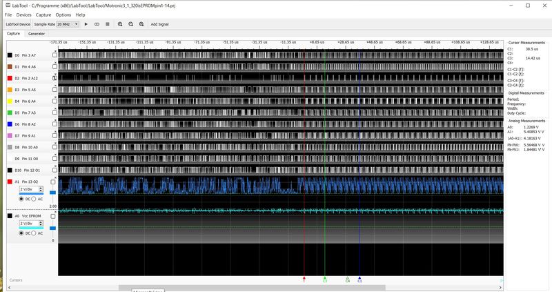
ADC removed in all graphs. I found no short and open circuits (used a magnifying glass) and all IC's have been replaced in the process. That is not to say that they have become damaged again in the process but still.
I don't know how to check the transparent latch or "the only other item is a NOR gate to generate the OE! for the EPROM".