After welding the disk, use a 4” angled disk grinder and carefully grind the weld flat, along with the .004” extra thickness of the disk material over the .090” thick telelever sheet metal. Be careful not to grind the remaining scribe mark for the new hole position. Place the large steel spacer back in position and carefully align the scribe marks with the hole and fully scribe the new position over the newly welded and ground surface. You will not be able to drill the new hole out to size accurately in one step. Instead, drill progressively to about 5/8” diameter and use a medium diameter round file to carefully complete the new hole bore using the scribe marks as a guide. This is really not as scary as it sounds and you can get quite accurate results with this method.
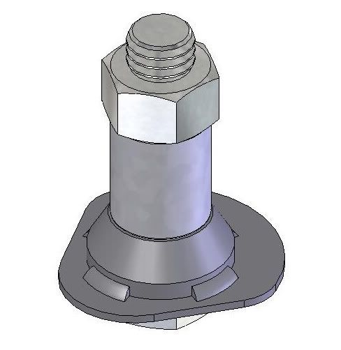
For gauging the hole size, take the 3/4” x 3” bolt you acquired earlier and use a small lathe to turn down the diameter to approximately .722” so that it just passes through the steel spacer hole. Try to shoot for about .002” clearance but no more than .004”. The closer the fit the more accurate your new hole alignment will be. Also, use the lathe to cut a 1-1/4” long section of a 3/4” metal pipe that will be used later as a spacer for a welding fixture. This piece can be cut by hand but be sure the ends are as flat as you can get them.
Now, you will be cutting out the new bottom plate from the .094” sheet metal you acquired earlier. Make a cardboard template to fit the cutout space on the bottom of the telelever arm. Be sure to overlap the cutout by about .050” to.100”. Lay the large steel spacer into position to get the correct height for the bottom plate. Cut away the template until you have the necessary clearances to fit the space. Trace the shape on to the new sheet metal and cut it out using a hacksaw and bench grinder. Use visegrips to hold the piece so that you won’t hurt yourself before you get a chance to try out this awesome mod to your bike.
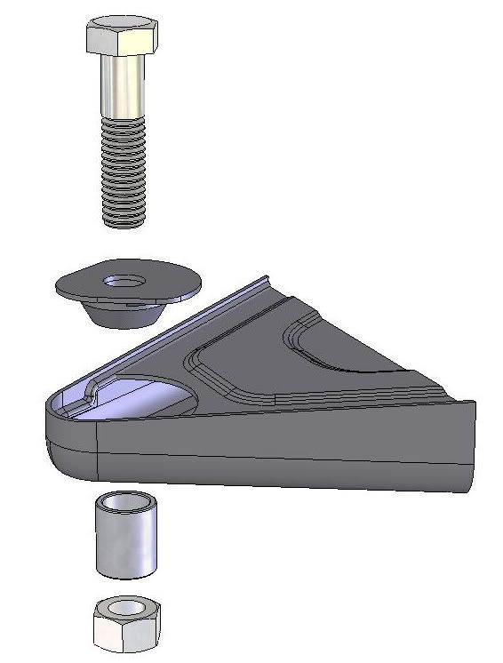
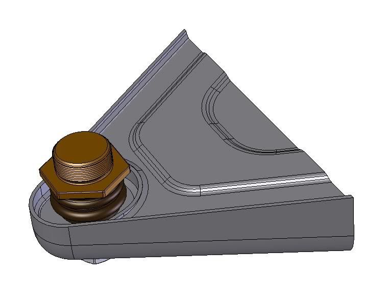
Carefully assemble the large steel ball joint spacer into the telelever arm and use c-clamps to hold the new cut out bottom plate together. Use the turned down 3/4” bolt to align the pieces through the top hole, clamp together with two c-clamps and scribe the hole on the newly formed bottom plate through the top of the telelever. Remove the parts and proceed to cut out the hole in the bottom plate just as described earlier for the new top hole in the telelever arm. Use the bolt and pipe spacer to make a welding fixture and weld the steel ball joint spacer to the new bottom plate. Stitch weld the steel ball joint spacer to the bottom plate in four equally spaced locations.
Place the new bottom plate assembly into the telelever arm and again use the bolt and pipe spacer to fixture the parts in place for welding. With everything bolted together tightly you should have perfect alignment of all the parts and are ready to tack weld the bottom plate in place.
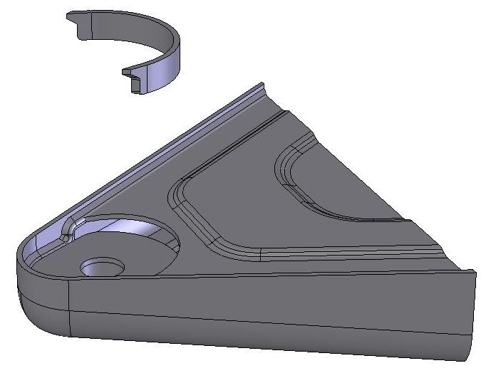
With the remaining .094” sheet steel plate, cut a rectangular strip about 1/2” wide to be used to complete and close the new assembly. You will need to bend this in a semi circle to fit on top of the bottom plate assembly you just welded in place and up against the circular cutout in the telelever arm. This is best accomplished using a hammer and any curved surface on your bench vise. Here is an assembly view of the curved plate ready to be placed into the telelever arm. Here is an assembly view of the curved plate ready to be placed on to the tack welded bottom plate in the telelever arm.
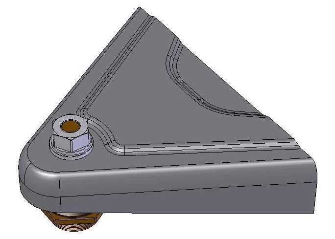
Use C-clamps to hold the curved plate in place and tack weld in a few spots before removing the clamps. Complete the welds on the back side of the curved plate and all around the new bottom plate. You want this to be weather tight so try to fill all the gaps. You will see that the completed telelever arm is at least as strong as it was originally, and this approach has in no way reduced the structural integrity of the arm.
You are now ready to prime and paint. I found that a semi gloss Krylon black paint was a good match to the original color. Not too sure about the durability of this paint but you can always have it professionally painted or powdercoated if you feel the need. Get your bike back together and try out it’s new awesomeness and spread the joy to another if you can. This job was a fairly time consuming and required some specialty tools, but it can all be done for less than $40 if you have access to the materials and tools needed. Happy Trails!
Finished 10mm shortened version top view:
Finished 10mm shortened version bottom view:
Note: If you have a steering damper mount you should also consider cutting and welding it 3/8” directly rearward on the telelever arm. This will assure the same action and travel of the steering damper as before in the stock position. When setting up your suspension after installing the new shortened telelever arm, you will now be able to take advantage of the 1.2 degree shorter rake angle and 3/4” shorter wheelbase. I have my front laden sag set to around 34-35mm and the rear at 32-34mm. For those of you that have the rear of your motorcycle jacked up to the moon, try lowering the clevis mount adjuster about 2-4 turns to start with, which will bring the seat height down 1/2”-3/4”. The result will still yield a steeper rake angle as well as a lower roll center. All of which contribute to a much better handling and easier to ride motorcycle.