|
|
|
|
|
| Author |
|
|
Registered

|
CIS to ITB EFI conversion
I own a 1975 911 Carrera 2.7L with CIS that I bought in 2006. The car had 41k miles and was largely all original. In nearly 17 years (and 30k miles) I have owned the car, I have made a number of modifications to improve performance and reliability to the engine (de-smog, SSI header/heat exchangers, Bursch muffler, Carrera 3.2 front fender mounted oil cooler/fan, free flow air filter housing and K&N air filter) and suspension (new Bilstein shocks, larger hollow torsion bars, larger adjustable sway bars) primarily.
In April of this year (2023) I attended the Luftgekuhlt 9 show at Mare Island in Vallejo, CA and came away convinced that I wanted do something with the Bosch CIS system (modify / replace) to make the engine bay look cooler and make more power. So I started searching the Internet. First I came upon Bitz Racing's CIS to EFI conversion kit - it has the EFI with a Megasquirt2 ECU, but didn't have the look. I wanted my engine to look like the Euro mechanical fuel injected 911 Carrera's with individual throttle bodies (ITB's). So I kept searching and I came upon x-faktory.com and their CIS to ITB EFI conversion kit. So I contacted Al (Kaz) at x-faktory and after many questions and answers I decided to purchase their Option #2 conversion kit. The Option #2 kit is the ITB EFI (Option #1) plus ECU control of the ignition advance. The Option #2 kit included the ITB's plus injectors and fuel rails, Megasquirt2 ECU plus wiring harness, fuel pressure regulator, MSD Streetfire CDI box plus fuel lines, vacuum hoses and manifold block, a fused electrical panel and copious installation instructions and links to all the information needed to successfully install the kit and get the engine running including a starter tune file for the ECU. In future posts I describe in detail the installation and tuning of the ITB EFI system. I ran the car on a chassis dyno before installation and the car made 175 hp max and 157 ft-lb max at the wheels. After installation and dyno tuning, the car made 192 hp max and 172 ft-lb max at the wheels (9.7% gain). Here are before and after photos of the engine bay:  
|
||
 09-14-2023, 05:02 AM
|
|
|
Registered
Join Date: Sep 2020
Posts: 409
|
Following
Sent from my iPhone using Tapatalk |
||
|
09-14-2023, 05:08 AM
|
|
|
Registered Minimalist
|
That's an impressive gain for just intake. People always talking about how intake wont make a difference on CIS pistons and cams. Wrong. Sure it's not ideal, but it makes a huge difference.
Al has really refined his ITB systems. Kudos to x-factory for making these kits.
__________________
Duane / IG: @duanewik / Youtube Channel: Wik's Garage Check out my 75 and 77 911S build threads |
||
|
09-14-2023, 05:39 AM
|
|
|
Registered
|
Part 2
In the list of items in the Option #2 (and #1) kit I failed to include the sensors - TPS (throttle position sensor - preassembled to the left side ITB assembly), the engine temp sensor, and the 2 bar MAP (manifold absolute pressure) sensor (located in the Megasquirt2 ECU housing, and an 8 bay electrical connector block (I purchased separately and used an additional 6 bay electrical connector block). It turned out it was a good thing that the x-faktory has a 4-6 week lead time from receipt of my order and payment to shipment of the kit as I had a steep learning curve to climb in order to be prepared for the installation and set up of the ITB EFI system. I have good electrical / mechanical ability and have been tinkering with cars since I was 15 years old. And in between working in engineering and engineering management in the semiconductor industry, I have taken coursework in modern automotive technologies, so I knew the basics but needed more specific information for this project. The first thing I did research on was the Megasquirt2 ECU which led me to DIYautotune.com (a leading distributor of Megasquirt ECU's) and on the website I found, purchased and read carefully the book titled Performance Fuel Injection Systems by Cramer & Hoffman (HP Books #1557). That book gave me not only a good overview but specific tips for wiring signal versus power, proper grounding, fuel lines and connectors, etc. The next thing I did was to search for and purchase a comprehensive, easy to read, color wiring diagram for the 1975 911 from Prospero's Garage (colorwiringdiagrams.com) 
|
||
|
09-14-2023, 10:01 AM
|
|
|
Registered

Join Date: Apr 2021
Posts: 33
|
What size throttles did you go with? 40mm?
__________________
74 911 backdate project 15 Macan Turbo |
||
|
09-14-2023, 11:18 AM
|
|
|
Registered
Join Date: Aug 2014
Location: Seattle
Posts: 95
|
Following! Impressive gain.
|
||
|
09-14-2023, 11:37 AM
|
|

|
|
Registered
|
Part 3
The ITB's are 40mm. The kit also came with a wide band O2 sensor, a 14Point7 O2 sensor interface unit, the throttle linkage and cross rod to connect to the stock throttle bell crank and filters and rain hats for the ITB's. So while waiting for parts to arrive I removed the SSI headers/heat exchangers and Bursch muffler and had an O2 sensor bung welded into the collector on the left header then re-installed the exhaust with new gaskets.  Next, with the wife on the throttle and me at the back car with a timing light, I characterized the ignition timing from idle to 6000 rpm. I did this so I could use the existing timing curve as a starting point for the ECU tune file.  Next I was off to the dyno shop to get a baseline for power / torque. |
||
|
09-14-2023, 03:36 PM
|
|
|
Registered
|
Part 4
Parts arrived and it was time to get busy. For the next 13 days (8-10 hrs/day), I worked to complete the tear down, install and debug. The plan was to work from the front of the car to the back. So I got busy and removed the fuel tank after running the car out of gas (note: there was still 2 gallons at the bottom of the tank, the feed line to the electric fuel pump comes out of the tank bottom and goes up 6 inches over the steering rack and back down the hard line back to the engine bay so the pump couldn't pull all of the gas out of the tank). Anyway, I drained the remaining gas by removing the drain plug and then pulled the tank. Once out of the car the tank got rinsed, then cleaned with a degrease / descaler solution, rinsed throughly then set out in the sun to dry for 3 days. While waiting for the gas tank to dry, I got busy removing the CIS unit and then cleaning the top of engine (I used WD-40, old cotton socks and a screw driver to get the grime out of the nooks and crannies). Next I rotated the engine manually to TDC on cylinder #1 making sure the distributor (dizzy) rotor was pointing to cylinder #1. I marked the position of the dizzy relative to the engine and then marked the position of the rotor on the dizzy. Then I removed the dizzy and again marked the position of the rotor on the dizzy. Once out, I disassembled the dizzy to reveal the mechanical advance and then used steel wire to wrap tightly around the posts holding the return spring on both sides of the dizzy thereby locking out the mechanical advance so that the ignition timing advance would be controlled entirely by the ECU. The dizzy was reassembled and reinstalled into the engine. |
||
|
09-14-2023, 04:12 PM
|
|
|
Registered
Join Date: Jul 2001
Location: mt. vernon Wa. USA
Posts: 8,753
|
Dan,
thank you for posting. it was a pleasure working with you on this project...your dedication to learning/understanding the system, combined with your organized, hands-on approach has really paid off. Congrats!! regards, al
__________________
[B]Current projects: 69-911.5, Previous:73 911X (off to SanFrancisco/racing in Germany).77 911S (NY), 71E (France/Corsica), 66-912 ( France), 1970 914X (Wisconsin) 76 911S roller..off to Florida/Germany RGruppe #669 http://www.x-faktory.com/ |
||
|
09-15-2023, 09:47 AM
|
|
|
Registered
|
Part 5
**Very important note I forgot to mention: after removing the CIS unit I put blue paper shop towels into each intake port to prevent debris from falling into the heads.** After the dizzy, I installed the Megasquirt2 ECU. I had seen others (Bitz Racing, etc.) suggest putting the ECU under the passenger seat and running the ECU wiring harness into the center tunnel, then out the back of the tunnel thru the firewall, but after looking into the tunnel thru the access hatch above the shift coupler and taking stock of everything already in that tunnel (wiring harness, fuel supply, fuel return, vapor, shift rod, parking brake cable, clutch cable and throttle rod), I decided to go a different direction. I used velcro strips to "attach" the ECU to the rib in the floor pan beneath the driver seat and then route the ECU wiring harness with the 1/8 inch ID thick wall vacuum hose for the MAP sensor located in the ECU enclosure thru a 3/4 inch hole I drilled in the firewall directly behind the ECU. I wrapped the wiring harness with electrical tape from the ECU connector to the end of the wires and taped the vacuum hose to the wiring harness before I fed the harness thru the hole in the firewall and brought the harness up thru space between the firewall and the rear shock mount cross brace so the ECU harness came out next to the factory wiring harness in the left front corner of the engine bay.  Next, I disassembled the electrical panel at the left rear of the engine bay and removed the factory CDI ignition module, drilled holes and mounted the MSD Streetfire CDI module in the same location. At that point I also removed the fuel accumulator and fuel filter and the accumulator mounting bracket so I could access the chassis ground lug behind the mounting bracket. Using 2 inch wide, 1/8th inch thick flat aluminum bar stock, I made mounting brackets for the ECU power panel, the fuel pressure regulator and the intake vacuum manifold and mounted those items to the rear shock mount cross brace. At this point the fuel tank had dried out completely, so I applied a thick coating of sealer paint to the exterior bottom of the fuel tank and the steel plate that mounts beneath the steering rack and let them dry for 2 days. Back to wiring: Now I addressed the wiring for the factory electrical components that were no longer being used (warm up regulator, throttle valve switch, cold start valve, thermoswitch for the cold start valve, factory CDI module) by un wrapping the engine wiring harness and clipping or removing entirely the unused wires. I also removed the wiring for the voltage regulator as my car had been fitted with a higher output replacement alternator with a integrated voltage regulator. I was careful to maintain the ground wires as the factory daisy chains the grounds from one component to the next. I chose to use the power wire to the heater blower motor, which was now also removed, to supply power to the ECU power panel as it had a 25 amp fused circuit and it was switched power, but it was also wired for starter cranking interrupt so I also had to clip the yellow wire from terminal 85 of its relay and connect terminal 85 directly to ground. I attached a red 10 gauge wire via a connector and ran that wire to the 12V in terminal of the ECU power panel. The ECU power panel is split with the upper half for ground connections and the lower half for power connections. I ran a black 10 gauge wire from the ground lug behind the accumulator mounting bracket to the ground in terminal of the ECU power panel. I installed the ECU's engine temp sensor where the thermoswitch had been located on the left cam chain cover. The MSD CDI ignition module requires direct connection to battery + and - for its high current connections, so I attached a red 10 gauge wire via a connector to the red MSD high current wire at one end and attached the other end to the battery cable terminal on the starter solenoid. I attached a black 10 gauge wire via a connector to the black MSD high current wire at one end and attached the other end to the chassis ground lug at the base of firewall near the starter which has a large webbed ground strap connected to the transaxle housing. Note: I used 10 gauge multi strand copper wire because I had it in hand left over from another project. 12 gauge multi strand copper wire would have been okay also. Now I rewrapped the engine wiring harness. I reassembled and reinstalled the factory power panel and I reinstalled the fuel accumulator and mounting bracket and installed a new fuel filter. The wide band O2 sensor and the 14Point7 O2 sensor interface module were mounted. The ITB assembles were installed after I used a Dremel tool to cut back the cooling air shroud (the outer footprint of the ITB's was larger near their vacuum ports than the CIS intake runners). I carefully vacuumed the intake ports, removed the blue paper shop towels and vacuumed again BEFORE I mounted the ITB assemblies to the heads. At this point the sealer paint on the fuel tank was fully dried so I took a break from wiring and reinstalled the fuel tank. I installed new fuel hoses (1/2 inch ID for fuel feed & 3/8 inch ID for fuel return) from the fuel tank over the steering rack to the hard lines running aft. I installed a new fuel level sensor and new fuel vapor lines in the front trunk. I filled the fuel tank with 2 1/2 gallons of fresh fuel and checked for leaks. There were no leaks, so I added 5 more gallons of fuel and reinstalled the cover plate beneath the steering rack. I reinstalled the battery and left the ground wire disconnected. Back to wiring: Al at the x-faktory preassembles the ITB assemblies so the injectors, the fuel rails and throttle position sensor (left ITB assembly only) were already in place. I removed the velocity stacks from each ITB assembly to give more working room and starting wiring power, ground and sensors to the ECU. I was careful to bundle sensor wires separately from power and ground wires. I used the 8 bay connector block for the sensor and Pertronix ignitor wiring and I used the 6 bay connector block for the fuel injector grounding connections to the ECU. Very Important: a 1kohm (.5 W) pull up resistor must be connected between the 12V supply wire to the Pertronix ignitor and the signal wire from the Pertronix Ignitor. See the attached photos of wiring diagrams and notes for more info.   
|
||
|
09-15-2023, 08:21 PM
|
|
|
Registered
|
Part 6
With the wiring connections to the ECU completed, I trimmed the unused wires in the ECU wiring harness. Below are photos of the wiring (note: at Al's suggestion I left the wires unwrapped until I had verified the connections and gotten the engine running - these photos were taken after dyno tuning)    Next I plumbed in the vacuum hoses. I used 1/4 inch ID vacuum hose to connect the vacuum port on each ITB to the vacuum manifold. I then connected the 1/8 inch ID vacuum line from then MAP sensor in the ECU housing to the vacuum manifold. Then I plumbed in the fuel lines using 3/8 inch ID Gates Barricade Fuel Injection hose (note: it is important to use fuel injection rated hose that can withstand the higher fuel pressure compared to fuel hose used with carburetors). I used a Dorman 800-301 fuel line repair tool to press a 1/4 inch to 3/8 inch barbed connector onto the factory installed 1/4 inch ID nylon fuel return line (I used a heat gun to soften the nylon line while I pressed on the barbed connector). For all the other connections (fuel filter to fuel presure regulator (FPR), FPR to fuel return, and FRP to injector fuel rails), I pressed on by hand the 3/8 inch barbed AN-6 fittings supplied with conversion kit and secured them with hose clamps. Now I turned my attention to the throttle linkage. First, I performed the course adjustment on each ITB assembly to ensure the front and rear ITB's were properly aligned to the center ITB (Al provides clear photo filled set up procedures from the x-faktory for all of this). Then I mounted the cross bar (adjusting the return spring on the left end of bar) and connected the linkage from the cross bar to the ITB butterfly valve shafts and from the cross bar to the throttle bell crank. I installed the factory throttle return springs and then adjusted the set up so I got wide open throttle when the throttle pedal was pressed to the floor. Now I went back and checked and tightened all of the bolts on the ITB assemblies (fuel rails, linkage support brackets, etc), the fuel line connections and every other bolt or screw I had touched in the engine bay. Lastly, I installed a new MSD ignition coil and connected the wires from the MSD CDI ignition module. The mechanical portion of the installation was now complete. |
||
|
09-16-2023, 10:15 AM
|
|
|
Registered
|
Part 7
With the mechanical work done it was time to start the software side of the project. From the X-Faktory: EFI kit for the 911 user manual, Install (Firmware) section on my notebook computer, I went to the EFI Analytics website (tunerstudio.com) and downloaded the TunerStudio MS Ultra program. I bought the full feature version instead of the no cost Lite version so I would have access to the VE Analyze Live - Auto Tune feature (more on that later) plus other features not available on the Lite version. I had also bought a 10 foot serial to USB cable so I could connect to the ECU. I loaded the appropriate driver for the serial interface. Back to the garage, notebook PC in hand. I had put the car's battery on the charger so to be fully charged when this time came. I disconnected the charger and reconnected the ground cable to the negative terminal of the battery. I put a towel on the roof of the car, then set up the notebook PC and connected the ECU (serial connection) to the PC (USB connection). I went to the engine bay and disconnected the fuel pump. I then switched the ignition to On which powered up the ECU. I launched the the TunerStudio program on the PC. From TunerStudio, I selected the File tab, then selected Create New Project which I named "DanN 75 911". Next, from the File tab, I selected Load Tune (msq) and loaded the tune file x-faktory had sent me.  Per the x-faktory user manual, I started inputting calibration data that was included in the user manual. Note, whenever you input data or make changes to existing data in the tune file you must perform the "Burn" function before the changes become effective. The Burn function flashes the modified tune file on the PC to the non volatile memory (flash EPROM) on the ECU. I performed the throttle position sensor calibration - which involved entering the resistance value of the TPS at 0% (throttle closed) and entering the resistance value of the TPS at 100% (throttle fully open). I input the engine temp sensor (CLT) calibration data, then noticed the CLT value on the gauge screen was reading 50 deg F while the temperature in my garage was 80 deg F at the time. I realized the thermistor calibration data didn't match with the thermistor in my engine, so I would need to generate new calibration data. This would take a while so I disconnected my PC from the ECU and switched the ignition to off. I disconnected the ECU to the temp sensor wire. I connected a digital multi meter (DMM) to the thermistor (red lead to thermistor and black lead to engine ground) to read the resistance of the thermistor. With an IR temp gun in hand, I used a heat gun to heat the thermisitor to 260 deg F, then shut off the heat gun and recorded the temperature / resistance as the thermistor cooled back down to room temp. I input the data into a spreadsheet and generated a scatter plot of the recorded data.  I picked high / medium / low data points and after reconnecting and restarting TunerStudio with ignition on, I entered the new CLT thermistor calibration data and burned the data. Now the temp reading on the TunerStudio CLT gauge matched the ambient temp in the garage (remember the engine is still off). I also entered the ignition advance data I collected from the stock set up into the Ignition Table. I completed checking and entering data into the tune file. In TunerStudio, the current state of tune data is the tune file named "Current Tune", I performed a Save As named with current date and time as a back up. Speaking of backups, TunerStudio creates "Restore Points" named by date and time whenever the data is changed and Burned in the Current Tune. These files are in the directory named Restore Points. Here are some of the tune file data. The VE, AFR and Ignition Timing tables are from after the dyno tuning.     Now it was time to begin testing the set up. First, with the fuel pump still off, I double checked the dizzy rotor was still pointing to cylinder #1 plug wire and the crankshaft pulley mark was still lined up with the timing mark on the crankcase. I cranked the starter and verified I was getting an RPM signal, the engine speed gauge on TunerStudio was reading 250 rpm. Now to check for fuel leaks and adjust the fuel pressure. With the ignition switched off, I reconnected the fuel pump wiring. I loosened the lock nut on the pressure adjusting screw on top of the FPR. I turned the ignition switch to on and fuel pump began running. I visually checked for leaks (there were none) and used a 4 mm Allen wrench to adjust the fuel pressure on the FPR gauge to 35 - 40 psi. Then I tightened the FPR pressure adjustment screw lock nut. I opened the hand throttle a bit and cranked the starter and the engine started albeit it didn't sound very good but it was a beginning. In TunerStudio, I selected Ignition Settings, then selected Ignition Options, then selected Fixed Advance and selected Fixed Timing. Then from Cranking Advance, I entered 6.0 (6 deg BTDC) and selected Burn. I connected my timing light and the timing was no where near 6 deg BTDC, so from TunerStudio, I selected Ignition Settings, then selected Trigger Wizzard and pressed the "+" button next to the Ignition Offset angle box until the timing as measured with my timing light measured the same as the timing advance the ECU was commanding. For my engine with a Pertronix ignitor in the dizzy, that required Ignition Offset angle turned out to be 61.5 deg, so I burned that value in the Trigger Wizzard. At this point, the engine sounded more composed but still off key. Next I went back to Ignition Settings, then Fixed Advanced and selected Use Table and selected Burn. A pop up message stated the ECU would need to be reset for the changes to take effect, so I turned the ignition switch to off, then turned the ignition switch back on and restarted the engine. I checked the timing with my timing light at several rpm levels and the physical timing was now tracking the ECU timing correctly. Next time: Balancing the airflow of the ITB's. |
||
|
09-16-2023, 05:01 PM
|
|

|
|
Registered

Join Date: Mar 2004
Location: North Vancouver bc
Posts: 5,294
|
most concise post ever. impressive.

|
||
|
09-16-2023, 05:32 PM
|
|
|
Registered
|
what did the kit from xfactory run you?
__________________
Instagram.com/timofthevalley |
||
|
09-16-2023, 06:08 PM
|
|
|
Registered
Join Date: Aug 2018
Location: Maryland
Posts: 2,271
|
Amazing write up!
__________________
83' Coupe - Ex-RaceCar 77' Targa Narrow Body - SC powered Copper Brown Metallic |
||
|
09-17-2023, 05:29 AM
|
|
|
Registered
Join Date: Jan 2011
Location: Gulf Coast FL
Posts: 1,493
|
Great job! Thanks for posting all the data, will help many in the future
|
||
|
09-17-2023, 07:52 AM
|
|
|
Registered
|
Answer to Aztim's question about price of the kit: per the q1-2023_pricing.pdf file I downloaded from x-faktory.com > Store > EFI > X-faktory EFI systems page, the price for the Option #2 kit was $5985
My total cost for the project was $8600 |
||
|
09-17-2023, 04:01 PM
|
|
|
Full Send Society
|
The ITBs from RHD are 2000-2400. Mega squirt is 500-700 depending on which one you want, the harness is about 100, the fuse panel, fuel regulator and associated bits are a few hundred.
I think in the carbs vs CIS vs EFI thread I broke down the raw parts cost to about $3600 The catch here if youre putting your own kit together is that youll need a base tune. Not all that hard to create or ask the forum to provide, but Als kit does come with a basic starter tune. Itll still need lots of adjustment but it gets you on base. I suppose its all relative to what you need/want and what your capacity for engineering and computer work you have. Sent from my iPad using Tapatalk
__________________
-Julian 1977 911 S: Backdate, EFI/ITB, AC project in the works: http://forums.pelicanparts.com/porsche-911-technical-forum/1106768-when-well-enough-cant-left-alone-backdate-efi-itb-ac-more.html |
||
|
09-17-2023, 05:00 PM
|
|
|
Registered
|
Part 8
Balancing the airflow of the ITB's. The first thing I did was replace the hex head M5-.8 x 20 mm adjustment screws for stainless steel M5-.8 x 20 mm cap screws so I could adjust the ITB's with a 4 mm Allen wrench which was/is easier for me to use in the tight confines at the base of the ITB assemblies.    For the front and rear ITB's, I used the lock nuts from RHD. For the center ITB's, I replaced the lock nuts with springs like those used for idle speed and idle mixture adjustment screws on carburetors. I made this change for 2 reasons: 1 - the spacing between lock nuts for the center and rear ITB's on the ITB assemblies was too tight for me to access both lock nuts with my mini 8 mm box / end wrench, and 2 - the center ITB adjusting screws are the idle speed adjustment which I wanted to be able to do with a single 4 mm Allen wrench. With the adjusting hardware worked out, it was time to balance the airflow of the ITB's. I started the engine and let it warm up so that it would idle without the hand throttle engaged. I connected my PC to the ECU and launched the TunerStudio app so I could access the gauge display and watch the engine speed (rpm).   While the engine was warming up, I loosened the retaining collar on each ITB and lifted off the velocity stacks / filter / rain hat assemblies and set the assemblies aside. Very Important: I disconnected the adjustable drop-links that connect the throttle cross bar to the ITB assemblies so that each ITB assembly could be adjusted independently.  I used an airflow meter to measure the airflow for each ITB.  First I would balance each ITB assembly matching the front and rear ITB airflow to the airflow of the center ITB by loosening the lock nut, then rotating the adjusting screw so the measured airflow was the same. This means I am moving the meter to the center ITB, check the flow. Then move the meter to the outer ITB and check the flow and adjust and then back to the center. Once I am happy with the flows, I tighten the lock nut on the outer ITB, then recheck the flow. I found that if I adjusted the outer ITB to a slightly higher airflow than the center ITB that when the lock nut was tightened, the adjusting screw would pull up slightly and the airflow would drop to match the airflow of the center ITB. With each ITB assembly's airflows matched front to back, I adjusted the center ITB of the each ITB assembly to match the airflows and set the engine idle speed (rpm). Then I loosened the lock nuts on the drop-links and adjusted the length of the each drop-link so that when I connected each drop-link to the throttle cross bar and carefully tightened the lock nuts on the drop-links that the engine idle speed and ITB airflows were unchanged.   With the ITB airflows balanced and the engine idle speed set, I reinstalled the velocity stacks / filter / rain hat assemblies.  Next time: Tuning the EFI. |
||
|
09-17-2023, 05:32 PM
|
|
|
Registered
|
Part 9
Tuning the EFI: After I got done balancing the ITB's, I took the car out for a drive first around my neighborhood and it ran okay, but definitely had some dead spots where the engine bogged and / or hesitated. Then I took it out of the freeway and it ran okay. So when I got back home, I started rereading the tuning guidelines in the x-faktory user manual and the user manual for the TunerStudio app. Because I had opted for the TunerStudio MS Ultra version, I had access to the Tune Analyze Live feature which would calculate and adjust the values in the volumetric efficiency (VE) table to make the actual air fuel ratio (as measured by the wideband O2 sensor) match the target AFR value on the tune file's AFR table. I decided to try out Tune Analyze Live. So I took the car out for another drive with the PC connected to the ECU and the Tune Analyze Live tool in TunerStudio running and updating the ECU as I drove. For this test drive, which lasted about 1 1/2 hours, I drove as many different combinations of rpm and load conditions as I could on surface streets as well as on the freeway. When I was done many of the problems I had noticed on my first drive were gone or significantly reduced.  Next I made an appointment to take the car back to the dyno shop for dyno tuning. The point of dyno tuning is that the tuner can drive the car on the dyno with very specific and controlled conditions especially for tuning of the ignition timing advance, air fuel ratio, VE table, and acceleration enhancement, etc. On the appointed day and time I took the car to the dyno shop for tuning. I turned the car over to the tuner. He secured the car to the dyno, set up cooling fans to prevent overheating, then started his tuning procedure. I walked down to the end of the shop to wait - it gets really loud standing next to a car running a dyno and I had left my ear plugs at home. After 2 hours the dyno tuning was completed. I paid the tuner and got a hard copy of the final dyno pull which showed a 9.7% gain over the baseline pull with CIS.  I drove the car home from the dyno shop and it was running very smooth. The next day, I took the car out for a shake down run around town and on the freeway and the car ran great. It now had more power from 2000 to 3500 rpm so it pulls away from stops more easily and it has a lot more power from 4500 to 6500 rpm so on the freeway the engine feels like it just wants to keep revving. In addition, the engine starts much easier when it's cold, it doesn't smoke on start up and it just runs a lot smoother. But then I took the car out for a first run in hills this last week and I discovered the limits of a 2 hour dyno tune - there are combinations of low rpm / mid to higher load that were not well characterized on the dyno and aren't quite right so the car shutters and hesitates. So I have more opportunities for improvements. Next week I plan to take the car back to same hill run, but I will have my PC and I will be running Tune Analyze Live. That being said, I am very happy with how this project has turned out. I always wanted to build my own hot rod and I got to do that with one of my favorite cars, an air cooled Porsche 911. And I get to continue working on it, improving it, learning from it, and most importantly having fun! |
||
|
09-17-2023, 09:41 PM
|
|


 P75
P75

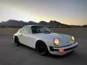 1975 Porsche 911s
