|
|
|
|
|
| Author |
|
|
Registered
|
3.2L RPM / Tach Signal for Wideband Datalogging
I've been reading thru the archives but haven't found a solution to an issue I'm having with the RPM input for the 14point7 SLC PP2 unit. There's quite a bit of old material related to the Innovate products, but this product is relatively new to these boards and electrical isn't exactly my strong suit so I'm hoping someone can dumb things down for me...
I've tried tapping directly from the DME unit (pin 21), and directly off the tach (pin 2) and get similar results (screen shot below). I have confirmed the unit is configured with the correct multiplier. Wondering if this a ground issue, or a weak signal? Something else? Any insight appreciated! 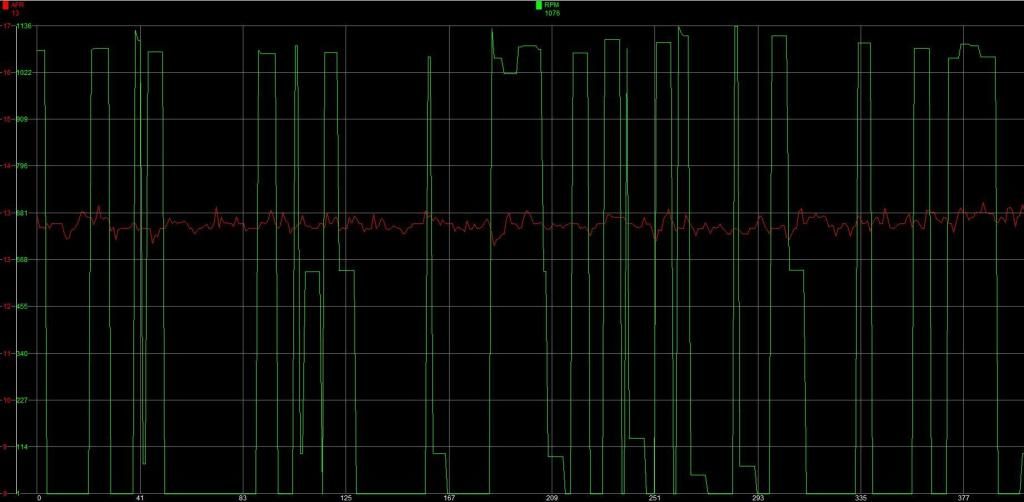 Andrew |
||
 01-26-2015, 10:32 AM
|
|
|
Registered User
Join Date: Oct 2012
Location: Lincoln, NE
Posts: 151
|
I bought that same unit and haven't installed it yet, so I'm very interested in what you find. Just going from experience on another car I built a MS setup for, that looks like noise to me. I'd investigate grounds and connection quality first.
__________________
1982 911 SC - 3.2, 17" 993 wheels, 993 interior, big red brakes. 1966 Corvair Sedan - 16" Superlight wheels, LED taillights, Euro H4 headlights. |
||
|
01-26-2015, 10:38 AM
|
|
|
Registered
|
I'm reaching out again for help because 4+ months later and I'm still trying to get this working -
I'm fairly certain that I have a grounding issue. I've been trying to different ground locations and combinations and I'm getting closer, but I still get interference for any RPMs outside of idle. The instructions tell me to ground the system to the ECU and the lamba sensor to chassis or block. I'm getting the best result so far grounding lambda directly to the block. Here's a quick log, you can see the RPMs zero out towards the end when I touched the throttle a couple times. Any ideas???? 
|
||
|
06-05-2015, 03:41 PM
|
|
|
Brew Master
|
I'm going to give this thread a bump just because I'm looking into buying one of these.
Doesn't the manufacturer offer any support for your problem? |
||
|
06-29-2015, 06:23 AM
|
|
|
Registered
Join Date: Jan 2015
Location: Redondo Beach, CA
Posts: 160
|
This may not apply to your situation but on most cars you can grab the tach signal from the negative side of the coil.
|
||
|
06-29-2015, 07:43 AM
|
|
|
Registered
Join Date: May 2002
Location: St Louis
Posts: 4,211
|
Do you have any info on what the input circuit to the "14point7 SLC PP2 unit" is?
__________________
Rick 88 Cab |
||
|
06-29-2015, 08:34 AM
|
|

|
|
Registered
|
I'm sure I can probably help. Let's take it offline. PM me if you want
|
||
|
06-29-2015, 11:04 AM
|
|
|
Registered
Join Date: May 2002
Location: St Louis
Posts: 4,211
|
why offline?
__________________
Rick 88 Cab |
||
|
06-29-2015, 11:23 AM
|
|
|
Brew Master
|
Quote:
|
||
|
06-29-2015, 11:52 AM
|
|
|
Registered
|
I didn't mean to offend anyone. I only suggested offline since I expect a lot of back and forth during the troubleshooting process with the OP that might be quicker through email or even phone.
Of course we would post any actual results or resolution back to the forum. |
||
|
06-29-2015, 02:14 PM
|
|
|
Registered
Join Date: May 2002
Location: St Louis
Posts: 4,211
|
Troubleshooting implies it once worked and from the responses I would say this is not the case.
An approach would be to determine if the interface between the DME and the logger is compatible. Dig out the Interface Control Document (ICD) 
__________________
Rick 88 Cab |
||
|
06-29-2015, 03:17 PM
|
|
|
Registered
|
Of course, I stand corrected....
|
||
|
06-29-2015, 03:25 PM
|
|
|
Registered
Join Date: May 2002
Location: St Louis
Posts: 4,211
|
Here is what is in the DME, upside down of course. I think the rising edge of pin 21 corresponds to a spark.

__________________
Rick 88 Cab |
||
|
06-29-2015, 03:30 PM
|
|
|
Registered
|
I should have updated this a few weeks back... Alan (the maker of the device) as a last ditch effort had me remove a tiny capacitor on the PCB labelled C19. I have no idea what it was for or why, but it worked and I had no issues picking up the RPM signal from pin21 on the DME which is the same as taking the single from the black/violet wire on the back of the tach. He said that once removed you would no longer have the option to pick up the signal from the low side of the coil or the injector ground. I had tried both these locations prior to the modification with no success either.
Unit works as expected now. |
||
|
06-29-2015, 04:56 PM
|
|
|
Brew Master
|
Quote:
|
||
|
06-29-2015, 06:16 PM
|
|
|
Registered
|
Quote:
I soldered new pick-ups directly to the DME unit for system ground (pin 5), RPM (pin 21) and simulated narrowband O2 (pin 24). You can also easily take your RPM signal right off the back of your tachometer. I added a molex connector to make removal of the DME easy for any servicing, etc. Alan didn't have a long enough cable for the O2 sensor so I extended it myself and soldered it directly to the PCB in the wideband unit to minimize the splices required. Only drawback is that the internal memory gets overwritten each time it's used. It would be nice to be able to store multiple sessions. Still a great product for the price. I can take a photo of the unit installed tomorrow if you like. Total cost was $275 (CAN $ if I recall correctly). |
||
|
06-29-2015, 07:42 PM
|
|
|
Registered
Join Date: May 2002
Location: St Louis
Posts: 4,211
|
I would be curious what the input to the data logger is. The waveform off the primary of the coil (200 Volts peak) is much different than the 12 Volt pulse train off of pin 21.
__________________
Rick 88 Cab |
||
|
06-29-2015, 07:43 PM
|
|
|
Registered
|
Quote:
|
||
|
06-29-2015, 07:46 PM
|
|

|
|
Registered
|
Quote:
|
||
|
06-29-2015, 07:49 PM
|
|
|
Brew Master
|
Quote:
|
||
|
06-30-2015, 04:57 AM
|
|


 1986 Porsche 911 Carrera

 1985 Porsche 911 Cab

