|
|
|
|
|
| Author |
|
|
Registered

|
How many seconds in a minute?
__________________
John '69 911E "It's a poor craftsman who blames their tools" -- Unknown "Any suspension -- no matter how poorly designed -- can be made to work reasonably well if you just stop it from moving." -- Colin Chapman |
||
 02-17-2009, 12:54 PM
|
|
|
Registered
|
 60 but i think 60 but i think at 6k RPM you will have 3k power cycles (inlet only open on power cycles) so that should read (6000/2)/60 or 6000/120 Gert
__________________
2008 Honda S2000 2003 C4S (Sold) 1975 911 S with some small modifications "Its good to plan your work, but its even better to do it" My Gallery |
||
|
02-17-2009, 01:03 PM
|
|
|
Registered
|
I don't think that power cycles matter in this case. We're only interested in one power cycle. If the engine turns over 6000 times in a minute, this is 100 cycles per second. So one rev (aka: 360 degrees) takes .01 seconds. Of this 360 degrees, 270 degrees (270/360 degrees) * .01 seconds would be the time during which the intake valve was open.
__________________
John '69 911E "It's a poor craftsman who blames their tools" -- Unknown "Any suspension -- no matter how poorly designed -- can be made to work reasonably well if you just stop it from moving." -- Colin Chapman |
||
|
02-17-2009, 01:48 PM
|
|
|
Registered
|
John,
I dug around and found this site. This formula supports your calculation above. t = (60/n)x(z/360) or t = z/(nx6) t = time in seconds n = crankshaft speed in RPM z = port open duration This eq to 0.00761s of port open time @ 6K RPM and 274 cam duration. Gert
__________________
2008 Honda S2000 2003 C4S (Sold) 1975 911 S with some small modifications "Its good to plan your work, but its even better to do it" My Gallery |
||
|
02-17-2009, 06:57 PM
|
|
|
Registered
|
Update on Flowbench
I have been working to get the flowbench finished and it is getting close, it took way longer than i thought, but should be able to finish this weekend and start with the calibration.
I also received the silicone and resin for making a mold of the port and CC. I will start getting ready to cast a copy of the head once i cleared up the mess in my garage. Cheers Gert    
__________________
2008 Honda S2000 2003 C4S (Sold) 1975 911 S with some small modifications "Its good to plan your work, but its even better to do it" My Gallery |
||
|
03-02-2009, 07:43 PM
|
|
|
Registered
Join Date: Oct 2004
Location: S California
Posts: 7,995
|
WOW - WOW
That flowbench is a work of art. Congratulations!
__________________
1970 911E Sportomatic Albert Blue 1971 911T Sunroof Coupe w/ Twin Plug 2.5 MFI 1973 911E Glacier Blue 1973 911E RSR Tribute Viper Green w/ 3.5 Twin Plug MFI |
||
|
03-02-2009, 10:00 PM
|
|

|
|
Registered

Join Date: Apr 2006
Location: northeast
Posts: 4,532
|
...lets hope that after he gets the fine art of flowing & tweaking heads understood that he will give ALL pelicans a great price to flow & tweak our cylinder heads as he ramps up his hobby business... ;-)
Best of luck here Gert!! A stunning looking cabinet for sure!! How many hrs & how much did all the parts cost to make this flow cabinet?? Bob
__________________
I live for 911 tweaks... |
||
|
03-03-2009, 05:13 AM
|
|
|
Registered
|
Hi
No matter what that device is capable of doing it definetly does looks awesome. A display of skill and devotion. Really looking forward to the actual flow testing. Jesper |
||
|
03-03-2009, 10:23 AM
|
|
|
Registered
Join Date: Jul 2001
Location: Portland Oregon
Posts: 7,007
|
Nicely done, Gert. My compliments to the "Chef".
Now,..........you're gonna learn some things,...
__________________
Steve Weiner Rennsport Systems Portland Oregon (503) 244-0990 porsche@rennsportsystems.com www.rennsportsystems.com |
||
|
03-03-2009, 02:57 PM
|
|
|
Registered
|
Thanks Steve et al,
I can not wait to start testing i have read so many articles, folmulas, threads and information in books that my head hurts and i have to start doing something with it Quote:
I think about $800 in the flowbench including the digital manometer and pitout tubes, and if i have to add it up about 50 hrs labor and about 20 hrs of research.
__________________
2008 Honda S2000 2003 C4S (Sold) 1975 911 S with some small modifications "Its good to plan your work, but its even better to do it" My Gallery |
||
|
03-03-2009, 07:33 PM
|
|
|
Registered
Join Date: Jun 2007
Posts: 182
|
Quote:
what do you measure with that tool? |
||
|
03-04-2009, 01:54 AM
|
|
|
Registered
Join Date: Jul 2000
Location: So. Calif.
Posts: 19,910
|
Quote:
To add to previous posts on turbulence, turbulence is desired only inside the combustion chamber, not in the port where high-velocity gas flow is desired. Correct me if I'm wrong here. In addition, while cutting off the valve guide flush with the port wall increases flow, fine for a dedicated track engine, the abbreviated valve guide also reduces valve stem stability and thus increases valve guide wear. YMMV. Sherwood |
||
|
03-05-2009, 05:27 PM
|
|
|
Registered
Join Date: Jul 2001
Location: Portland Oregon
Posts: 7,007
|
Hi Sherwood,
A few observations, if I might. Quote:
Quote:
This is a very complex subject with a lot of variables. Quote:
__________________
Steve Weiner Rennsport Systems Portland Oregon (503) 244-0990 porsche@rennsportsystems.com www.rennsportsystems.com |
|||
|
03-05-2009, 11:00 PM
|
|
|
Registered
Join Date: Jul 2000
Location: So. Calif.
Posts: 19,910
|
Hi Steve,
thanks for your astute answers, as always. I'll have to agree with you in regards to encouraging turbulence in the A/F mixture in the non-squish chamber. However, if the ridges from the cutter promote needed turbulence in the intake port, why then have them in the exhaust ports where turbulence isn't a requirement? Sherwood |
||
|
03-06-2009, 01:07 AM
|
|
|
Registered
Join Date: Jul 2006
Location: S. Florida
Posts: 7,249
|
The way I understand it is the ridges in the intake port create a thin boundary layer of air rolling along the surface of the port called surface turbulance, while the air just above the surface of the port is shooting right on through never touching or dragging on the surface of the port.
It's almost as if the air tumbing along the metal surface is like a lubricant for the air moving along quickly just above it because it keeps that air from dragging on the surface of the port. If the port was perfectly smooth that wouldn't happen and the airflow would drag along instead of tumble right at the surface. The tumbleing surface turbulance also keeps fuel atomized that may wet out on the surface of a smooth port. Especially on carburated and CIS cars. Rough surfaced intake ports flow a little more air than polished smooth intake ports because of this. The ridges in the exhaust port will probably fill up with carbon in short time and not have any effect. |
||
|
03-06-2009, 11:37 AM
|
|
|
Registered
Join Date: Jul 2001
Location: Portland Oregon
Posts: 7,007
|
Quote:
The tooling marks are simply the result of the cutter working on the alloy and truly hard to eliminate in the exhaust port without almost doubling the costs. If the machine tool needs to make 4-5 more passes with smaller tooling, its simply adds to the cost and I've not seen a benefit to the additional expense to make it worthwhile doing. I suppose if those tiny ridges really bothered someone, some time with a mild flapwheel would make them happy,...
__________________
Steve Weiner Rennsport Systems Portland Oregon (503) 244-0990 porsche@rennsportsystems.com www.rennsportsystems.com |
||
|
03-06-2009, 05:37 PM
|
|
|
Registered
|
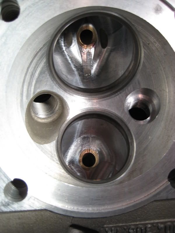
Update
Flowbench is now fully done with digital manometer installed and all the velocity probes hooked up. I will wire the garage with the 220v feed and will hopefully be ready to start testing this weekend.
In the mean time i made a mold of the port and CC and will cast a copy of the head to start working with.   There has been some good information from the threads above and what i have taken from that is that the inlet surface finish and port shape is very important to promote good high speed flow, keep fuel in suspension and introduce swirl with the port shape to promote A/F mixture and combustion with the lazy ports. The exhaust port finish is not that important for flow (i.e. doesnot have to be a mirror polish) but could have some benefits if polished i.e. carbon is less likely to stick to port walls and also some heat reflection. While creating the mold i measured the port volume and it came to 129cc on a centerline lenght of 3.6" This gives an average cross sectional area of 2.18"^. Some information for interest Below is the output of the PipeMax program based on my engine configuration and an estimated inlet flow of 236.25 CFM @ 28" as Kenikh had in the thread of the S registry in the beginning of the thread as a target. These numbers are probably not accurate until it can be corrected to a known or measured engine output but still provides some indications. From the average CSA above it seems like the port size (CSA) is still ok and should yield ~260Fps @28" (Maybe someone can comment on this) The VE in this case was calculated based on the total induction flow of 236.25 CFM. (TBC when i have things hooked up to the flowbench) 82.651 Cubic Inches @ 7800 RPM with 126.8 % Volumetric Efficiency PerCent Required Intake Flow between 234.9 CFM and 248.0 CFM at 28 Inches Required Exhaust Flow between 184.7 CFM and 199.7 CFM at 28 Inches ------- Piston Motion Data ------- Average Piston Speed (FPM)= 3602.30 in Feet Per Minute Maximum Piston Speed (FPM)= 5870.11 occurs at 75.584 Degrees ATDC Piston Depth at 75.584 degree ATDC= 1.2228 inches Cylinder Volume= 220.1 CC Maximum TDC Rod Tension GForce= 3053.55 G's Maximum BDC Rod Compression GForce= 1734.86 G's ------- Current Camshaft Specs @ .050 ------- IntOpen= 28.00 IntClose= 60.00 ExhOpen= 49.50 ExhClose= 17.50 Intake Duration @ .050 = 268.00 Exhaust Duration @ .050 = 247.00 Intake CenterLine = 106.00 Exhaust CenterLine = 106.00 Compression Duration= 120.00 Power Duration = 130.50 OverLap Duration = 45.50 Lobe Center Angle (LCA)= 106.00 Camshaft installed Straight Up = 0.00 degrees -Minimum Intake Valve Lift to prevent Choke = .521 Lift @ 7800 RPM Minimum Exhaust Valve Lift to prevent Choke = .505 Lift @ 7800 RPM - Induction System Tuned Lengths - ( Cylinder Head Port + Manifold Runner ) 1st Harmonic= 30.867 (usually this Length is never used) 2nd Harmonic= 17.519 (some Sprint Engines and Factory OEM's w/Injectors) 3rd Harmonic= 12.231 (ProStock or Comp SheetMetal Intake) 4th Harmonic= 9.627 (Single-plane Intakes , less Torque) 5th Harmonic= 7.811 (Torque is reduced, even though Tuned Length) 6th Harmonic= 6.571 (Torque is reduced, even though Tuned Length) 7th Harmonic= 5.671 (Torque is greatly reduced, even though Tuned Length) 8th Harmonic= 4.988 (Torque is greatly reduced, even though Tuned Length) Note> 2nd and 3rd Harmonics typically create the most Peak Torque 4th Harmonic is used to package Induction System underneath Hood ------- Operating RPM Ranges of various Components ------- Camshaft Intake Lobe RPM = 7123 Exhaust Lobe RPM = 5889 Camshaft's Intake and Exhaust Lobes operating RPM range = 4815 to 6815 Note=> Lobe RPMs are only BallPark estimations Minimum Intake Valve Lift to prevent Choke = .521 Lift @ 7800 RPM Minimum Exhaust Valve Lift to prevent Choke = .505 Lift @ 7800 RPM Current (Intake Valve Curtain Area -VS- Time) Choke RPM = 7521 RPM Current (Exhaust Valve Curtain Area -VS- Time) Choke RPM = 7563 RPM Intake Valve Area + Curtain Area operating RPM Range = 5448 to 7448 RPM Intake Valve Diameter RPM Range = 5521 to 7521 Intake Flow CFM @28in RPM Range = 6183 to 8183 __________________________________________________ _________________________ Best estimate RPM operating range from all Components = 6051 to 8051 Note=>The BEST Engine Combo will have all Component's RPM Ranges coinciding __________________________________________________ _________________________ --- Cross-Sectional Areas at various Intake Port Velocities (@ 28 in.) --- 182 FPS at Intake Valve Curtain Area= 3.104 sq.in. at .502 Lift 185 FPS at Intake Valve OD Area and at Convergence Lift = .492 229 FPS 90% PerCent Rule Seat-Throat Velocity CSA= 2.464 sq.in. at 7800 RPM 350 FPS Velocity CSA= 1.609 sq.in. at 7800 RPM Port Sonic-Choke with HP Loss 330 FPS Velocity CSA= 1.708 sq.in. at 7800 RPM Port Sonic-Choke with HP Loss 311 FPS Velocity CSA= 1.812 sq.in. at 7800 RPM Smallest Useable Port CSA 300 FPS Velocity CSA= 1.879 sq.in. at 7800 RPM Recommended Smallest Port CSA 285 FPS Velocity CSA= 1.978 sq.in. at 7800 RPM Recommended Smallest Port CSA 260 FPS Velocity CSA= 2.168 sq.in. at 7800 RPM Recommended Port CSA 250 FPS Velocity CSA= 2.255 sq.in. at 7800 RPM Recommended Port CSA 240 FPS Velocity CSA= 2.349 sq.in. at 7800 RPM Largest Intake Port Entry CSA 220 FPS Velocity CSA= 2.562 sq.in. at 7800 RPM Largest Intake Port Entry CSA 210 FPS Velocity CSA= 2.684 sq.in. at 7800 RPM Torque Loss + Reversion 200 FPS Velocity CSA= 2.818 sq.in. at 7800 RPM Torque Loss + Reversion Cheers Gert
__________________
2008 Honda S2000 2003 C4S (Sold) 1975 911 S with some small modifications "Its good to plan your work, but its even better to do it" My Gallery |
||
|
03-11-2009, 08:12 AM
|
|
|
Registered
|
Gert;
You're making great progress. It looks like you've got a lot of data and calculations there -- the trick will be to sort through it all and pick out what what's important and what doesn't really tell you anything new. A couple of specific questions and comments that came up as I read through your latest post. While creating the mold i measured the port volume and it came to 129cc on a centerline lenght of 3.6" This gives an average cross sectional area of 2.18"^.I'd beware of using "average cross sectional area" since it's not the average cross section that affects performance so much as the minimum. That being said, port volume is important to know, but I'd measure the volume all the way up the pipe to the butterfly, and then the trumpet tip. Once the air column is in the intake track, it doesn't care if it's in the head, in the throttle or carb body, or in the case of WOT in the trumpet. But I found it interesting comparing the cylinder volume to the intake volume. If you were to dump all of the mixture from the intake into the cylinder, what would happen to the pressure in the intake track? ------- Current Camshaft Specs @ .050 -------What cam shaft design are you using? Best estimate RPM operating range from all Components = 6051 to 8051This sounds about right for a full-race engine. --- Cross-Sectional Areas at various Intake Port Velocities (@ 28 in.) ---I don't understand what this set of data tells you. Especially given that everything is at 7800 RPM. BTW, I'd take a look at the model data at your expected torque peak. I believe that this will be key to making the engine strong. Above the engine's peak torque speed, it's just a case of declining returns, and trying to prop-up the curve as long as you can. Below the engine's peak torque engine speed will have a big impact on how driveable an engine is. If you design the engine around "peak HP", that means you're optimizing it's performance within about 500RPM-1000RPM of the engine's rev-limit. In your case this would be 7000-8000 RPM. This is a relatively uncommon situation and you'll risk having the engine be a dog at anything except that very narrow rev range. There are relatively few places on most race track where you'll be pulling those sorts of rev's for any amount of time (Road America and ovals excepted).
__________________
John '69 911E "It's a poor craftsman who blames their tools" -- Unknown "Any suspension -- no matter how poorly designed -- can be made to work reasonably well if you just stop it from moving." -- Colin Chapman Last edited by jluetjen; 03-11-2009 at 08:51 AM.. |
||
|
03-11-2009, 08:47 AM
|
|
|
Registered
|
Hi John,
I will be using the DC62 Cams on 106 LCA. They are not full race cams but fairly "hot" I used the average CSA to get a calculated average flow potential for the whole port and is based on some CFM number chosen, in this case Kenikh's head flow numbers as they are known and can be acheived. This will give a target for the runners and the carb and what i deducted from the program is that they calculate VE % for the whole tract and can use that as a comparitive target when i test it on the flowbench. The rate of flow will vary at each CSA down the port for the same CFM ( in this case they calculated a value @ 28" simulating peak HP, not sure what they used or how they calculated that and mapped the velocities for a range of CSAs) and in my case the minimum will be (40mm) 1.94 sq in. What i read of the table at the end of the data stream is that at the minimum CSA point I will be @ 278 Fps, the ave CSA puts me @ 260 fps and i am still in the acceptable CSA range before i get into trouble with too big a port. These are for me at the moment some data points that i can somehow relate to i.e. have known variables like pressure to test at and velocity numbers. I can perform order of magnitude comparisons to at least give me some ideas where i am at. The formula that we used in the calc above yields a dynamic velocity number (in my case i think it was 285fps) but i don't know at which pressure to do a comparative test to measure that against on the flow bench, so its hard for me to use that as a target, maybe i am missing something and there is a way to do it . Gert
__________________
2008 Honda S2000 2003 C4S (Sold) 1975 911 S with some small modifications "Its good to plan your work, but its even better to do it" My Gallery |
||
|
03-11-2009, 10:11 AM
|
|
|
Moderator

Join Date: Dec 2001
Posts: 9,569
|
Gert, great stuff!
To add to John's questions, how can the intake and exhaust lobe rpm be different given that our engines are SOHC, i.e. both lobes are on the same camshaft. Maybe that doesn't make a difference in the calculations. John, I think the final table shows the port velocity at various port cross sectional areas and the impact on performance at a fixed RPM. Since you cant show a three-variable analysis without a graph, I think that is why RPM is held constant and the velocity varied with area.
__________________
'66 911 #304065 Irischgruen 96 993 Carrera 2 Polarsilber '81 R65 Ex-'71 911 PCA C-Stock Club Racer #806 (Sold 5/15/13) Ex-'88 Carrera (Sold 3/29/02) Ex-'91 Carrera 2 Cabriolet (Sold 8/20/04) Ex-'89 944 Turbo S (Sold 8/21/20) |
||
|
03-11-2009, 10:22 AM
|
|
 |
| Thread Tools | |
| Rate This Thread | |
|
|


 1969 Porsche 911E 2.0 E
 1975 Porsche 911