|
|
|
|
|
| Author |
|
|
Registered
|
Howto adjust cam timing, timing advance ??
I am in the last process of completing my engine after a rebuild. I have the dial indicator and Z block.
Do I need to first adjust clearance for all the valve's first, then use dial indicatior for #1 and #4 ? I have a 930 engine with updated SC grind profile 930 cams. According to wayne's book, timing for 930 with SC cams is same as SC timing ???? Or any other suggestions/experience? Is there anyone that has a nice procedure of how to set correct timing? How do I use dial indicator? |
||
 03-09-2010, 03:27 AM
|
|
|
Registered
Join Date: Oct 2008
Location: Nash County, NC.
Posts: 8,556
|
You set the engine with the crank pulley on Z1
Cams are with the dot or 930 to the top then install the pin and retainer bolt or 46mm nut on both sides. Chains are inplace, cam gears, pins and bolts, and tensioners also. Adjust the intake valve to .1 mm and load the Zblock and install the dial guage. Pre load the dial guage about half way so there is tension against the valve retainer and set the outer rim to the end of the pointer for zero. Cam spec is .9 to 1.1 mm with 1.0 being optimum I prefer to shoot for the high side of the spec 1.1 because of chain stretch. everything loaded, turn the crank pulley 360 degrees to Z1 This will cause the intake valve under the dial guage to start moving at about 30 or 40 degrees before TDC and the dial guage will move so you start watching the dialguage and the up coming Z1. This is the point you want the 1.1 reading to set. Remove the big nut and if you dont have the thread for the pin to pull, a top of a sparkplug will work. 17mm open end on the flats of the cam, pull the pin and find the hole near where the pin was to replace the pin for 1.1+ so you can get the pin in the proper hole for 1.1 and load against the pin in direction against the cam movement. If your 1.1 doesnt come in where you want it reload the pin. Anywhere is spec is is good, the high side is great but this is you working number for the match of the other cam. Lock your finished product, turn the crank 2 revolutions and you ll come back to the measurment on the dial guage you set. Go to the other side #4 and set the valve. Load everything again like you did on #1 and go through the same steps. If you cant get really close to match the other side in the 1.1 mm setting you need to remove the tensioner and outer gear and move the gear in the chain one cog and put it all together. This will give you all new measurments to look for and set to. At this point your cam is near the desired setting, set the pin for the reading you want. Pre load the pin and read the setting number. Note, if you cant get into .15mm of the desired setting you ll need to move the gear inside the chain another tooth. You really want to be within a couple hundreth mm of the #1 setting This might not be 100% clear but close enough to get the idea. Bruce |
||
|
03-09-2010, 06:22 AM
|
|
|
Registered
|
Not sure if I understood completely, but I kind of did (i think)
Will adjust the valve clerance and mount up the dial indicator and try it out |
||
|
03-09-2010, 12:28 PM
|
|
|
Black and Blue

Join Date: Jul 2000
Location: Austin, TX USA - Ya'll
Posts: 2,556

|
I had some trouble understanding this procedure as well, but it finally sank in after a couple of shots at it. My dial indicator is not metric, so I had to understand what the numbers actually meant on the dial indicator.
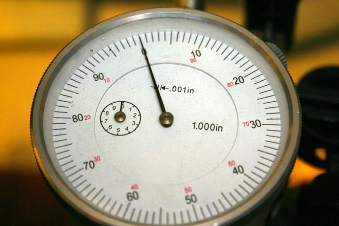 For me, 40 ticks equals 1mm. Also, I was abit thrown off when it started going in the negative direction. I had to readjust the depth of the indicator to drop down instead of up as the cam rotated. Once I got the dial indicator understood and properly secured, I set the engine back to TDC and put the dial indicator arm on the ZERO and started turning the crank. At about the 330 degree mark, the dial indicator started moving. I stopped turning the crank at 0.04" which was actually the 60 tick on my dial. Keeping the cam at that position, I removed the cam nut and pulled out the pin. then I moved the crank to Z1 and put the pin back in along with the cam washer and nut. Now you just repeat the procedure for #4. keep in mind that 360 degree from TDC on #1 is actually TDC for #4. I hope this helps, it was dreadfully confusing until I actually did it. you do have Waynes book right?
__________________
Kemo 1978 911 SC Non-Sunroof Coupe, two tone Primer Black and SWEPCO Blue, Currently serving as a Track Whore 1981 911 SC Sunroof Coupe, Pacific Blue Project, Future Daily Driver |
||
|
03-09-2010, 02:06 PM
|
|
|
Registered
|
yups, reading in waynes book now to get the better understanding. :-)
thanks |
||
|
03-09-2010, 02:44 PM
|
|
|
Registered
|
Bruce. So I should go for 1.1 with my SC spec cam on my 930?
|
||
|
03-09-2010, 03:27 PM
|
|

|
|
Registered
|
1. Set the crank at TDC.
2. Rotate both cams so that the dot or the 930 is at 12:00 or straight up. 3. Insert the pin in both cam sprockets where it will fit. 4. Set the valve lash on #1 to proper clearance (.004") 5. Install the dial indicator on the intake valve retainer on cylinder #1 and pre-load it. 6. Zero the face of the indicator. 7. Turn the crank clock-wise about 3/4 turn and look for the intake valve to start opening. 8. Continue to turn the crank until it is at Z-1 and stop. 9. Loosen the cam bolt and remove it, the big washer and the stake pin. 10. While making sure the crank stays at Z-1, rotate the cam until you observe the proper lift on the dial indicator (1mm in your case). 11. Replace the stake pin in the hole that lines up along with the cam bolt and big washer. 12. Rotate the crank at least eight times around and re-check the dial indicator. It should match the 1mm reading you set it to at TDC. 13. If it matches after turning the crank eight times, stop at TDC, remove the indicator and repeat the timing for cylinder #4. The main idea is that the intake valve is starting to open as the exhaust valve is closing as the piston is approaching top dead center. The timing of this sequence is critical. You want the intake to be 1mm open when the crank is at TDC on the overlap stroke. Note that you should only have rockers installed on intake #1 for the left cam and then intake #4 for the right cam AFTER you set the left. Hope this helps. Lindy |
||
|
03-09-2010, 03:31 PM
|
|
|
Registered
|
Thanks for feedback.
Think I get the understanding now. Was out in the garage and tried it out, seems like I need some adjustments. Will continue tomorrow. Thanks guys for helping out :-) |
||
|
03-09-2010, 03:44 PM
|
|
|
Registered
|
Quote:
Doyle
__________________
Recording Engineer, Administrator and Entrepeneur Designer of Fine Studios, Tube Amplifier Guru 1989 Porsche 911 Carrera Coupe 25th Anniversary Special Edition Middle Georgia |
||
|
03-09-2010, 04:36 PM
|
|
|
Registered
Join Date: Oct 2008
Location: Nash County, NC.
Posts: 8,556
|
If you just have regular SC cam grind, the spec is for the cam .9 to 1.1. The cam is for Carrera
also and the Carrera gets loaded at about 1.5 in contrast, but that number is from memory instead of off the info as is the SC spec. Bruce |
||
|
03-09-2010, 05:47 PM
|
|
|
Registered
Join Date: May 2003
Posts: 3,346
|
930 engines have small ports. Therefor I'd advance the cams to the spec for the small port SC engines. This is about 1.2-1.5mm. This will give better torque at low RPM before the boost kicks in. High RPM power is not a problem with a 930
 -Andy
__________________
72 Carrera RS replica, Spec 911 racer |
||
|
03-09-2010, 10:04 PM
|
|
|
Registered
|
Think I forgot to mention that my 930 intake ports has been ported to 35mm.
Does this matter for my setting? What would the best setting be? |
||
|
03-10-2010, 01:58 AM
|
|
|
Registered
Join Date: Oct 2006
Location: MYR S.C.
Posts: 17,335
|
yes, the needle goes in the CCW direction. just read the red numbers. DO NOT do like someone did mine. mine were suppose to be set at .020". they set them so the needle pointed to the BLACK .020, which was really .080.
__________________
86 930 94kmiles [_  _] RUNNING:[__] NOT RUNNING: ____77 911S widebody: SOLD _] RUNNING:[__] NOT RUNNING: ____77 911S widebody: SOLD88 BMW 325is 200K+ SOLD 03 BMW 330CI 220K:: [_ _] RUNNING: [__] NOT RUNNING:01 suburban 330K:: [_ _] RUNNING: [__] NOT RUNNING:RACE CAR:: sold |
||
|
03-10-2010, 04:37 AM
|
|
|
Registered

Join Date: Sep 2009
Location: Virginia
Posts: 83
|
I have a simple procedure (with photos) in my engine assembly handbook that may help you. Pretty sure you can download it now on the cheap and the photos are pretty good. It is only focused on assembly though, in a lot of detail, but no other info on disassembly, checking components, etc. You will find good "real world" info on 911 assembly.
Try the link below, or you can find it at my Scrogham Consulting site on Facebook (or through Synergy Racing): Porsche 911 Engine Assembly Guide by Cole Scrogham in Reference |
||
|
03-10-2010, 05:30 AM
|
|
|
Black and Blue
Join Date: Jul 2000
Location: Austin, TX USA - Ya'll
Posts: 2,556
|
After reading Lindy's post, I like that method the best. Its much easier to simply spin the cam. Next time...ill know

__________________
Kemo 1978 911 SC Non-Sunroof Coupe, two tone Primer Black and SWEPCO Blue, Currently serving as a Track Whore 1981 911 SC Sunroof Coupe, Pacific Blue Project, Future Daily Driver |
||
|
03-10-2010, 09:02 AM
|
|
|
Registered
Join Date: Aug 2008
Location: Palatine, IL. (N/W Chicago Burbs)
Posts: 208
|
Perfect timing guys, on this subject.
I myself, will be setting cam timing this weekend. Two things? Bruce, are you saying that I should set the cam timing to 1.1 mm (the high end) instead of shooting for 1.0 mm (center) on my stock 906/06, 79 911sc? Also, How important is it to get the cam (wave) washer centered. It seems like theres some slop here? Leakproof.
__________________
Restoring/Rebuilding Yellow Canary '79 911SC Suspected track car |
||
|
03-10-2010, 07:58 PM
|
|
|
Registered
Join Date: May 2004
Location: Boulder, Colorado
Posts: 7,275
|
Leaky
You don't need to get the big washer exactly centered, but what you do have to do is to be sure that none of its edges extend out beyond the cutout on the gear. When it is flattened out by the torque on the nut you want it flat on the gear. It can't do that if it is overhanging that lip. This is not hard to deal with - just be observant. And this is pretty close to being centered. Walt |
||
|
03-10-2010, 11:05 PM
|
|
|
Registered
Join Date: Oct 2008
Location: Nash County, NC.
Posts: 8,556
|
I always shoot for the high number but the truth be known you ll accept where the left number comes in and do your best to accept the right number.
Then there is always EXACTLY where the case center line and the Z1 mark is and how it it lining up. Line to line is a judgement call especially if youre getting frustrated with setting the second cam. Bruce |
||
|
03-11-2010, 05:34 AM
|
|
|
Registered
Join Date: Dec 2003
Location: Centreville, MARYLAND
Posts: 938
|
Go to harbor frite and buy two digital dial indicators and get another z block. Then do the left, tighten nut 3/4 then do the right. Then you can forget about counting needle sweep revolutions.
__________________
Old Tee all 911s sold |
||
|
03-11-2010, 07:23 AM
|
|
|
Registered
Join Date: May 2004
Location: Boulder, Colorado
Posts: 7,275
|
Most times I have set cams it has been without the fan housing installed. I don't know if that is better or worse. You can use the case centerline as case TDC. That way you aren't relying on the housing, locating pin, and whatnot being spot on. On the other hand, the fan housing gives you a mark which is closer to the notch on the pulley, and you aren't squinting through two notches to line things up.
I have seen assertions that the pulley TDC can be off some. That it is best to establish a TDC mark on the flywheel, and use that. I tried that, but didn't see enough difference to continue on the engine in question. A larger source of frustration can come from the pin. The pin is not what holds the cam timing in place. The partial teeth (early engines had a full circle with full holes back there, but that stopped at some point) are not strong enough for this. It is the friction between the parts imparted by the torque on the big nut (or small nut, in the later cams) which holds things where you set them. If this friction is not strong enough, the hardened pin can strip the inner teeth. So it is the timing with the nut firmly set (not necessarily at final high torque, but well tightened so it won't change when you put the big torque wrench to it) which counts. And the pin and its vernier system do not locate things precisely. You can get 0,020-0.030" (which will vary with cam slope) of difference within the same pin setting. You can prove this to yourself easily by inserting the pin, holding (as needed) the crank, and waggling the cam holder tool to and fro and watching the dial change. So getting spot on calls for getting the pin in a suitable hole, and also holding the reading while snugging and at least partially torquing the nut. I think getting exactly (based on the resolution of your dial indicator) the reading you are shooting for on both cams is a result of either luck or incredible patience. One can take comfort from the fact that the factory gives a tolerance for the overlap setting. Walt |
||
|
03-11-2010, 11:36 AM
|
|


 Porsche 911 Turbo
 Porsche 911 Turbo

 Grenade
 Grenade

