|
|
|
|
|
| Author |
|
|
Registered
Join Date: May 2004
Location: Boulder, Colorado
Posts: 7,275
|
CIS vacuum source for MAP sensor
Can I use the black (per manual should be blue) distributor vacuum hose (source below butterfly) for this? Ting into that line would be the simplest. (my distributor's vacuum unit has two, the other red hose coming from above the butterfly)
What about Ting into the brake booster line where it emerges from the left side of the plastic housing? I'm also thinking of drilling a hole in the plastic plenum part of the air box in the vicinity of the brake booster and installing a small barbed fitting, either threaded or epoxied into the hole. My plastic box has a nice tube on its left side, perfect for plugging the MAP sensor's rubber bushing in, but I realized it just connects to the backside of the air filter! |
||
 04-25-2021, 02:23 PM
|
|
|
Registered
Join Date: Apr 2018
Location: Louisville,Ky
Posts: 192
|
I ran mine straight off of a throttle body port. Whatever used to hook up to that port has long ago been deleted.
__________________
3.4,K27,Andial IC,Sc cams,Ported heads,Electromotive Ign,Twin plug,Leask Wur,RarlyL8 zork,GHL headers,Simplified CIS,Ported fuel head,Fikse wheels,Etc.Go hard or go home |
||
|
04-28-2021, 10:55 AM
|
|
|
Registered
|
Quote:
__________________
911 SC 3.0, 1982, black, US model with own digital CPU based lambda ECU build and digital MAP based ignition control All you need to know about the 930/16 and 930/07 Lamba based 911 SC US models: https://nineelevenheaven.wordpress.com/english/ |
||
|
04-28-2021, 10:36 PM
|
|
|
Registered
Join Date: May 2004
Location: Boulder, Colorado
Posts: 7,275
|
FWUR and MicroSquirt into a NA 3.0 US SC
Andrew - I was hoping this was the answer. The red vacuum line starts above the throttle butterfly, along with the idle bleed air port. The blue vacuum line starts somewhat below the butterfly shaft.
I'm hoping that effects like a venturi (if the TB where the butterfly is located is shaped to produce any of that effect) won't mess up the signal, and it will be the same as if I drilled a hole into the plastic plenum below it. Or at least vary proportionately, as I can adjust the graph. And I just T'd it in. I have had to work hard to use only, or almost only, existing wiring. I've got the board tucked away in an old Volvo Bosch Lambda system case, which physically is the same as the US SC case. It has three more prongs for the 35 pin plug, but alas the plug only has the 11 the SC has. Don't know if I can purchase the female fittings to add those extra three, but there are options - there is a convenient place to drill a hole in the front. Now if I can figure out how to find or duplicate the 8 pin male plug to the acceleration enrichment module (I'm using the wires to it from the ECU, and from it back to the engine, as part of my wiring scheme, so need to connect most of the ins to outs) I can avoid butchering the insides of that module, so I'll be able to swap back and forth with only a little unhooking and hooking up of plugs on the engine. Helps that I don't need the back up lights or the heater blower - that gives me three wires through the 14 pin plug. Next to load the FWUR firmware, and start setting the parameters. 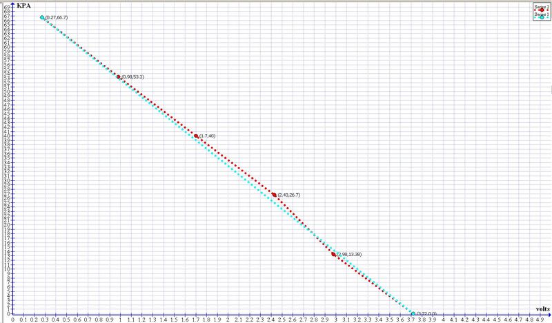  Testing the MAP sensor was made a bit difficult because the small vacuum pump couldn't easily be set right on one of the (mmHg, converted to KPA) marks on the dial. I'm planning on using a standard SC oil temp sensor - I have three spares. The 150*C pair came out pretty close (my alligator clips didn't work as well as grounds as I might want), and the IAT is pretty much a straight line, so that may be a good start. Any of this (other than the 200*C temp sensor) look rather wrong? |
||
|
04-28-2021, 11:15 PM
|
|
|
Registered
|
What is your specific target/aim here?
__________________
911 SC 3.0, 1982, black, US model with own digital CPU based lambda ECU build and digital MAP based ignition control All you need to know about the 930/16 and 930/07 Lamba based 911 SC US models: https://nineelevenheaven.wordpress.com/english/ |
||
|
04-29-2021, 11:05 PM
|
|
|
Registered
Join Date: May 2004
Location: Boulder, Colorado
Posts: 7,275
|
To optimize performance on the race track - get WOT AFRs in what - the 12.5-13 range? Emissions and fuel economy not important. No need for careful mapping of all engine states, but should start easily and idle fairly well, though 1,000 rpm idle is just fine. Racing class rules allow the alternate ECU and WUR, but require stock FD, injectors, etc.
Tracks range from sea level to about 6,000 feet in elevation. Using the 3mm adjustment screw and a completely stock US '82 SC system (oxygen sensor disconnected) last fall at around 500 feet elevation I had the car running more or less in the 12s. Without change last weekend in Colorado at a bit over 5280 feet, it was running in the 11s. Felt strong, ran smoothly enough, etc, but had to be giving up some power. On reflection, I may have the X and Y axes for the IAT sensor reversed. But I am getting ready to test the DIY board installed in a Bosch case, preparatory to installing in the car. |
||
|
05-03-2021, 10:50 PM
|
|

|
|
Registered
|
Using a map sensor like approach would mean you would have to read the vacuum and provide that signal to a device cpapble to affect the mixture.
Thats not possible with the factory state of the car, means with the built in ECU and sensors attached to the engine. What you could do is getting an innovate controller and use its 0-1v narrowband simulated output to feed the original ECU – AND ... using the throttle switch's "accaeleration" state to drive a relay which leads the other analog signal/wire from the Innovate controller which normally provides the 0-5v wideband signal to the ecu. Here via Innovate software you can do a hack and tell the controller to provide via that wire a narrowband 0.2-0.8v signal when an AFR of 12.5:1 is read via the WB sensor. Another approach could be using my digital ECU where you can use the narrowband sensor without an additional purchase of an WB controller. Here you can set which duty cycle should be set when hitting the gas, means the throttle body butterfly switch's acceleration threshold. There via Software you can set it to 55, 65, 70 or whatever static Dity Cycle is needed to give you the proper 12.5:1 AFR / 0.85 Lambda. In my experience and tests I figured out that at a present Lambda 1 resulting duty cycle an increase of the dutycycle by +25% switches from stoich Lambda 1 to Lambda 0.85. And tahts what you want.
__________________
911 SC 3.0, 1982, black, US model with own digital CPU based lambda ECU build and digital MAP based ignition control All you need to know about the 930/16 and 930/07 Lamba based 911 SC US models: https://nineelevenheaven.wordpress.com/english/ Last edited by AndrewCologne; 05-04-2021 at 01:58 AM.. |
||
|
05-04-2021, 12:54 AM
|
|
|
Registered
Join Date: May 2004
Location: Boulder, Colorado
Posts: 7,275
|
Andrew - I tried last year to use the stock CIS ECU, but wired the WOT switches to activate a PWM (and disconnect the stock PWM source) which would give a duty cycle I could change by pressing buttons. It should have worked, but didn't. It may be I just didn't realize I needed to do something else to get the controlled PWM up to the required voltage.
When I lamented this state of affairs, Tony (Boytoy) asked why I wasn't just using the FrankenWUR and DIY ecu? So that's where I am - As soon as I program that ECU I can remove the stock ECU box and plug this replacement box in. I post here because I haven't found any discussion of significance on the 911 fora, but there is a lot here, though it appears only by guys with turbos (who have more incentive, I think, as CIS and turbo boost control isn't as good as NA CIS is). The only thing I want from my wide band O2 sensor is to record levels. I don't want the sensor controlling anything. I don't trust them that much. My understanding is that once I get the ECU programs dialed in, then between the FrankenWUR frequency valve (fuel injector) and the stock FV, I can have optimum power WOT values, and the system will automatically adjust for changes in barometric pressure (either at the track I am racing on during the day/weekend, or due to tracks at different altitudes). I'm adding a barometric sensor, which the DIY ECU has provisions for. My question on April 25 had to do with the vacuum source for a MAP sensor. At present I am Td in to the blue distributor vacuum line, which gets its vacuum from below (though not awfully far below) the butterfly. If I had been a bit more observant, I might have skipped the FrankenWUR, as it appears the DIY ECU can, through control of the stock FV, do the stuff I want to do with the stock WUR in place. But the Franken is a nifty looking device. Walt |
||
|
05-04-2021, 03:05 PM
|
|
|
Registered
|
Quote:
So ... it MUST be controlled to affect the duty cycle that way so a mixture with a resulting lambda of 0.85, optimal for accel. will be present. The K-jet mixture is anything but not flat through all revs. If you connect the DMM to the testport and take a ride you will see that the DMM reports a much lower duty cycle if the revs go up and throttle gap gets bigger. Means ... the mixture will be too rich at higher revs which will be compesated by the Lambda control. And thats exactly your problem you reported in the past, wenn i.E. a given duty cycle of 30% cycle is calculated by the ECU to achieve Lambda 1 – a sudden acceleration and therefore jump to the ECUs "static" 65% duty cycle, will end up in a too rich mixture, means non "optimal" for accelerating. I figured out, that a shifting of a (lambda 1 resulting) duty cyle by +25%, will result in a more or less Lambda 0.85, means your target you want when accelerating. So ... if driving at 3000 RpM where i.E. a given duty cycle of 30% would result, here when accelerating, a static duty cycle of 55% would result in a perfect Lambda 0.85 Lambda mixture, and not 65% as done by the factory ECU. Seee what I mean? So ... if you really wont the lambda control to be switched off, at leat you must know what duty cylces in your engine at a given RpM/load "would" result (for a mapping), to therefore use the specific duty cyle at a speciifc RpM/Load which will result in the perfect Lambda 0.85 accell. mixture.
__________________
911 SC 3.0, 1982, black, US model with own digital CPU based lambda ECU build and digital MAP based ignition control All you need to know about the 930/16 and 930/07 Lamba based 911 SC US models: https://nineelevenheaven.wordpress.com/english/ Last edited by AndrewCologne; 05-05-2021 at 04:38 AM.. |
||
|
05-05-2021, 04:25 AM
|
|
|
Registered
Join Date: May 2004
Location: Boulder, Colorado
Posts: 7,275
|
VE Table
Andrew - isn't getting the accelleration AFR to be optimum what one does with the VE table or the like in a system like the DIY?
  My experience (based on what a tuner told me) with tables like this for my Electromotive EFI system on another 911 is that for racing you don't have to adjust all of the cells - just the ones for WOT mainly. So I will have to do some tuning, on a chassis dyno, and perhaps based on what I record on the track (assuming I get to trust the AFR readings from the Innovate). That seems to be what the Turbo guys who populate this discussion seem to be doing, though they are in a position to share settings with each other. I tried your sort of Level 1 system of altering the relationship between the throttle switch settings (ground or not ground) and the ECU/PWMs without any additional components - basically just some changing of connections and forcing grounds, but like the more complicated system I tried to create, I must have done something wrong, as I didn't see a change in what I saw on the Innovate screen. I set things up with three switches so I could use stock, Cologne, or Fricke. The DIY is a step up, as it allows you to change the PWM much more granularly than just the stock fixed (if not using the O2 sensor) system. But if I mess up the DIY system, it won't work well either. Hence the questions, and my gratitude for answers from people like you who have a lot of expertise with CIS and variants. My Electromotive system has both MAP and TPS. I don't see an easy way of adding a TPS to a stock 911 CIS throttle - maybe there is one? The DIY can deal with inputs from both, which might be quite advantageous, especially for accelleration? |
||
|
05-05-2021, 11:09 AM
|
|
|
Registered
|
I dont know to what DIY system you're refering to.
Quote:
Quote:
Ok, but then you need an additional transistor or better mosfet which is capable handling at least 6-7 Amperes when switching the ground signal to the FV by the PWM generators resulting PWM/duty cycle. But that should be the easy part of the task. Maybe thats why it didn't work? Not shure if I understood you right there. But nevertheless, you need a 2D map where you can see which value of Duty cycle will result at Lambda 1 at a given Rpm AND load. With that table you can then force the PWM generator to duplicate each specific resulting dutycycle value --> +25%, which more or less gives you the wanted 0.85 lambda. See what I mean? Quote:

__________________
911 SC 3.0, 1982, black, US model with own digital CPU based lambda ECU build and digital MAP based ignition control All you need to know about the 930/16 and 930/07 Lamba based 911 SC US models: https://nineelevenheaven.wordpress.com/english/ Last edited by AndrewCologne; 05-06-2021 at 04:40 AM.. |
|||
|
05-06-2021, 04:38 AM
|
|
|
Registered
Join Date: May 2004
Location: Boulder, Colorado
Posts: 7,275
|
Well, I am using MicroSquirt (developer board), an offshoot (lower capabilities) of Megasquirt, as an ECU. Sold by an outfit with DIY in its name, which is what the originator of this discussion (for turbos) suggests for his Franken WUR. Which substitutes a PWM modulated fuel injector for the spring system the Bosch WUR uses to control/set the pressures before the FV takes over (and the MSqt system also controls that FV).
Not using TPS, for the reason given. How did you hook up a TPS to your Bosch TB? But MAP ought to substitute well enough? The system has a switch pin for fuel - regular vs some alcohol - but I haven't hooked that up. It can be O2 sensor controlled (or at least auto tuned), though I haven't wired things for that either - just have the Innovate O2 output run into the replacement ECU so it can log AFRs. Just as I have the Tach output of this system run into (when I figure out the right pin numbers) the Innovate, hoping it will work (adding a variable resistor never worked for me, and without the benchmark of RPM or speed on the Innovate data I can't figure out where I am and what I am doing, other than that low AFRs mean acceleration, and high spikes mean off the throttle and braking?). May be more complicated than the system you are using. Discussion of some other system here suggests that other system didn't work out well, but I don't think it was referencing the system you use. But I'm kind of committed unless I toss my ~$600 US investment. And replacing the WUR should mean never having to fiddle with setting CP/WCP mechanically at the WUR, or messing much with the 3mm screw. The reason I don't have a lot of faith in the Innovate is because what I see is sort of all over the place with the stock CIS. In particular, the idle, with the car idling pretty smoothly, varies repetitiously by half a point (applying 1 second smoothing) just sitting on the grid. And from time to time the trace recorded just disappears from the graph. Sometimes, after some period of time, it reappears. I can understand that with stock settings (including the '82-3 acceleration module) the AFRs could be expected to vary between WOT, from various RPM starting points to various, up to but not always, 6,250 rpm, or 7,000 approaching some corners. But it doesn't seem to be especially consistent. At the moment all is academic, as I can't get the tuning program to recognize, via a serial port, the device/firmware. But that is a different matter. And I am wiring things so I can fairly easily swap back and forth the Bosch ECU system (stock) and the FWUR + MicroSqt system. |
||
|
05-06-2021, 05:48 PM
|
|

|
|
Registered
|
Hi Walt,
I dont know anything about Microsquirt or even Megasquirt, so I cant follow you here regarding its specific features/capabilities. I'm using the original factory TPS, means the one giving the contacts at approx. 15° and approx. 35° degrees throttle butterfly position. This one is enough for letting the system working properly. Cause ... wanted the mapping here would not be archieved via a new TPS with muche more contact points, .... but via a manifold vacuum sensor which is also an indicator for a given load of the engine. And thats where your initial question refers to. ... if I got you right here. Regarding the Innovate product. Im not using the Innovates application for watching the lambda/afr, but just reading the 0-5v signal via my own device where I never have problems as it shows always the actual lambda at all loads and revs. Yesterday I was driving my Digi ECU with wideband sensor attached where on acceleration with open throttle beyond 35° the mixture and therefore lambda gets forced to stay at 0.85 while accelerating. In combination with an own electronic/cpu controlled ignition/spark management I am able to use individual ignition curves wehre you clearly can feel the benefit of the combination of optimal ignition advance and perfect fuel mixture. (here in the currect state the ignition curve is only rev affected –as common–, means no load till now is taken into account, but ... I'm on it. As here the manifold vacuum which normally goes to the dizzys retard port will be used for that.)
__________________
911 SC 3.0, 1982, black, US model with own digital CPU based lambda ECU build and digital MAP based ignition control All you need to know about the 930/16 and 930/07 Lamba based 911 SC US models: https://nineelevenheaven.wordpress.com/english/ Last edited by AndrewCologne; 05-10-2021 at 01:30 AM.. |
||
|
05-10-2021, 01:26 AM
|
|
|
Registered
|
Hi Walt,
additionally regarding the vacuum connections of the throttle body of the SC with 930.16 engine usable for map sensoring ... I correct my statement above that the lower connection on the throttle body front for the ignition retard of the dizzy can't be used for MAP sensoring as directly when accelerating from idle the vacuum drops to zero, which would mean a full load which would be useless. This vakuum does exactly what its meant to be: lettng the dizzy move to approx 5° ATDC only at idle at factory state. So when leaving idle it does not affect the ignition advance and therefore the engines preformance. The vacuum connection which actually can be used for map sensoring is the lower one on on the back side of the throttle body. Here as factory default the hoses for the deacceleration valve and the cruise control are connected via a T-connector. Just unplug the hose of the T-connector if no cruise control or the function of the deacceleration valve is needed and put on a separate hose to connect to a MAP sensor. I used the hose of the dizzys retard connection and sealed its open connection of the throttlle body using a plug. As you can see below at idle and approx 800-900 RpM it provides 45 kpa which is optimal. If more kpa's do result, then its an indicator for an existing false air leak between the throttle butterfly and combustion chamber. On the right of my application you can see the kpa/load, below the RpMs and the advance. The load based table on the left will be included with their values the next days and here has no effect, till now the advace is only affected by the RpM. Also the presence of this manifold vacuum does perfectly correspond the engines load as you can see in the video below when driving with accelerating and deaccelerating.
__________________
911 SC 3.0, 1982, black, US model with own digital CPU based lambda ECU build and digital MAP based ignition control All you need to know about the 930/16 and 930/07 Lamba based 911 SC US models: https://nineelevenheaven.wordpress.com/english/ |
||
|
06-01-2021, 02:38 PM
|
|
|
Registered
Join Date: May 2004
Location: Boulder, Colorado
Posts: 7,275
|
Andrew - Thanks for straightening this out. However, I am a bit uncertain (since I don't have cruise control) as to which hose.
The obvious one is the ~7.5mm OD black cloth outer fabric vacuum hose which connects to the left side of what the parts catalog calls the vacuum limiter - 930 110 190.00, #15 in the diagram.  Is that the deceleration valve? That would be the most likely candidate for the simple T and hoses the catalog shows for the cruise control parts. But it doesn't come out very low on the throttle body. However, if its purpose is to give full vacuum to the device(s), should be good, and is (engine is on ground but not out of car completely at moment) easy to get to. I'm about to make the change over (all designed to be reversible pretty easily), and of course don't want to make a mistake with what perhaps is the most important control of the system - the MAP. I know I'll make other mistakes, but I hope they will be in the programming, which can easily be fixed once identified. Walt |
||
|
06-30-2021, 10:40 PM
|
|
|
Registered
|
Quote:
And this connection on the back side of the throttle body to #15 provides the proper connection for a map sensor. See the values in the video above of my developed MAP ignition software and hardware which handles the ignition advance, means the signal from the dizzy to the CDI.
__________________
911 SC 3.0, 1982, black, US model with own digital CPU based lambda ECU build and digital MAP based ignition control All you need to know about the 930/16 and 930/07 Lamba based 911 SC US models: https://nineelevenheaven.wordpress.com/english/ |
||
|
07-15-2021, 03:39 PM
|
|
|
Registered
Join Date: May 2004
Location: Boulder, Colorado
Posts: 7,275
|
Thanks - I'm battling my other mistakes, so it is good to have confidence that I plugged the MAP sensor into the right place.
Walt |
||
|
07-16-2021, 11:26 PM
|
|


 Volkswagen Bug - Split window
 Porsche 911
 Volkswagen Bug - Oval window

