|
|
|
|
|
| Author |
|
|
Registered User
Join Date: Apr 2013
Posts: 2
|
another reference/speed sensor thread
Hi there. I'm in the middle of replacing reference and speed sensor connectors on the harness side, i already bought and installed new ref. and speed sensors. I am chasing a no start condition on an '84 944 NA.
The harness side has yellow in the end, black in the middle, and the shielding wire at the other end, however the sensor side pinout has yellow as the middle pin. Does that seem right? I even have a spare wiring harness and it has the same pinout on the harness connector; yellow,black, shielding. old sensors too are black, yellow, shielding. |
||
 04-19-2013, 08:24 PM
|
|
|
Proprietoristicly Refined
Join Date: Jul 2001
Location: ~Carefree Highway~
Posts: 5,833
|
This is an old picture of mine---it may help??
 Make sure you connect the speed and reference sensors to the correct wire DG or BG Speed and Reference Sensors - Checking, Replacement, and Adjustment No Start? Before or after the sensor change--- "Does your tach needle bounce 1/16th of an inch while you crank the engine? GL & welcome to Pelican J_AZ
__________________
1988 924S, 85,750K ..+ 1987 924S, 154K DD (+15K est. bad odo) |
||
|
04-20-2013, 05:14 AM
|
|
|
Registered User
Join Date: Apr 2013
Posts: 2
|
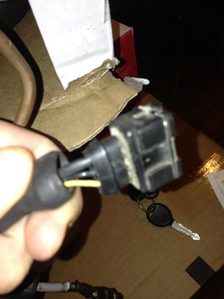 thanks John, I got the same diagram from clarkes garage and disassembled the old reference sensor to see what is what, however the problem lies in the above. this is a picture of the harness side of the connector, as you can see on the sensor, the yellow is in the middle while on the harness, the yellow is on the end. is this the way its supposed to be? |
||
|
04-22-2013, 11:46 AM
|
|


