|
|
|
|
|
| Author |
|
|
SharkHead

|
Comments on a workaround invited
I did a re-wire from 14 pin down under a few years ago...all is good.
I've been doing typical maintenance and found that I have, at idle, aprox. 13.9 V at jump post but at the CP the three leads that come from the Jump post measure 13.4V. The wires are warm and harder than they should be...should have replaced during the re-wire I suppose. Comments on this please: I am considering using the same wire type (12mm), since I have leftover, from the post to the CP in lieu of having 4mm wire at hand. I will run it into the cabin and then split it into three equal bundles to connect to the female connectors and plug into the CP. Thoughts please! 
__________________
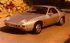
'79 928, 85k Opal Metallic '99 BMW 540i, 97k Titanium '72 BMW 3.0 csi, 85k km (euro Deutschland '82) Taiga |
||
 12-11-2013, 01:49 PM
|
|
|
Recovering dismantler
|
Quote:
4G has a surface area of approx 21 mm. 12g is only 3.3mm. So it would take approx 6 12 ga wires to carry teh same load as one 4g.
__________________
Neil 2009 Mini Cooper 2004 Mercedes CLK500 2024 Subaru Outback Touring XT 2020 Entegra Coach |
||
|
12-11-2013, 02:10 PM
|
|
|
SharkHead
|
My reference to mm is from the 928 current flow diagram. It shows the Alt wire to the jump post as 10mm and the three that go to the CP as 4 mm.
However, If I choose to use the same wire that is used from Alternator to Jump post for Jump Post to CP I would breakdown the strands into three equal bundles to connect at the CP. Thanks, Jon
__________________
'79 928, 85k Opal Metallic '99 BMW 540i, 97k Titanium '72 BMW 3.0 csi, 85k km (euro Deutschland '82) Taiga |
||
|
12-11-2013, 02:15 PM
|
|
|
Recovering dismantler
|
Quote:
__________________
Neil 2009 Mini Cooper 2004 Mercedes CLK500 2024 Subaru Outback Touring XT 2020 Entegra Coach |
||
|
12-11-2013, 04:13 PM
|
|
|
Network Native

Join Date: Jan 2007
Location: SoCal
Posts: 10,349
|
Why not clean and redo the connectors, the wire inside hasn't changed resistance. Difference could also be your ground reference points.
|
||
|
12-11-2013, 05:21 PM
|
|
|
SharkHead
|
I'm losing voltage down the run...wires are hardened/corroded heating dropping current. Grounds are clean.
__________________
'79 928, 85k Opal Metallic '99 BMW 540i, 97k Titanium '72 BMW 3.0 csi, 85k km (euro Deutschland '82) Taiga |
||
|
12-11-2013, 07:40 PM
|
|

|
|
928: Serial Enabler
Join Date: Sep 2007
Location: Elkhart, Indiana
Posts: 2,929
|
Makes sense. Once the wires corrode internally they need to be replaced.
__________________
84,85,86 928 cars |
||
|
12-12-2013, 06:32 AM
|
|
|
928-Electrics Guy

Join Date: Jun 2007
Location: Phoenix AZ
Posts: 715
|
What you propose is almost the best way to do it. Porsche actually screwed up with the 3 separate wires from Jump Post to CE panel - it is an awful feeder implementation - it should always have been a single big wire! So yes do it.
I'm sure Porsche chose to do this (against better judgement) since its cheaper and easier to route 3 smaller wires through the boot. However if any of the 3 wires makes a bad contact or degrades - all the current flows through the remaining wires overloading them (maybe you had this). A single 12mm (either conducting core diameter or area mm^2) wire is good. however at the end dont split it into 3 (creates the same issue) ... make a single attachment plate that can bolt to the CE panel with a large single wire connection to it (crimped or soldered) Alan
__________________
1994 928 GTS Black/Black Manual Last edited by Alan in AZ; 12-12-2013 at 02:16 PM.. |
||
|
12-12-2013, 06:47 AM
|
|
|
SharkHead
|
Alan,
I like that suggestion. Thanks, Jon
__________________
'79 928, 85k Opal Metallic '99 BMW 540i, 97k Titanium '72 BMW 3.0 csi, 85k km (euro Deutschland '82) Taiga |
||
|
12-12-2013, 10:17 AM
|
|


 1979 Porsche 928
 1972 BMW 3.0 csi
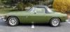 1974 MG MGB
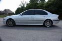 my beater 540i
 1981 928
 1984 928 S Euro
 1986 928S

