|
|
|
|
|
| Author |
|
|
Registered User
Join Date: Feb 2017
Posts: 49
|
Crankfire Ignition/Nutek -
Hello - does anyone out there know anything about an older crankfire system called Nutek Firepower EIS? I am getting ready to reinstall an engine after a rebuild and really have no idea on the ignition timing and wondering if it is worth just taking it out and putting in new - which still doesn't get me comfortable w/ timing the ignition. Supposedly all the curves are pre-programmed and fire with magnetic pickup from imbedded mags in the crank pulley. Assuming the cam profile is the same, would it be ok to just put it back to work with the programmed curves? Is there a way to test if all coils are firing etc? Thanks
|
||
 03-18-2018, 09:58 PM
|
|
|
It's a 914 ...
Join Date: Jan 2008
Location: Ossining, NY
Posts: 4,809
|
I have one of these in my vintage racer 911. I believe its from approx. 1993. Ive had good luck with it so far. The company is long since out of business, so Im not sure what Ill do if I ever need parts like a new coil or trigger sensor. Re: the timing curves, I recall that mine is adjustable using some nobs on the unit. I have the manual from mine. Let me know if youd like a scanned copy.
To your q about testing the coils, you could test each spakplug for spark. Im sure there are more comprehensive tests you can do. Perhaps others will chime in on how that can be done. Scott Last edited by stownsen914; 03-19-2018 at 05:23 AM.. |
||
|
03-19-2018, 05:17 AM
|
|
|
Registered User
Join Date: Feb 2017
Posts: 49
|
Scott - THANK YOU - I have a receipt (I bought the car from FLA about 2 years ago) and the receipt is from 1994! I would love a copy of it if you would be so kind - Nice to know someone else is out there - have you ever had to time it? There are curves and the guy provided the curve info - just dont know anyone that would be able to interpret it for me to know if any changes need to be made or if it is appropriate for the set up I have. Thanks again for the response.
|
||
|
03-19-2018, 07:17 AM
|
|
|
It's a 914 ...
Join Date: Jan 2008
Location: Ossining, NY
Posts: 4,809
|
Quote:
As to timing, I think I may have made a small adjustment after I got the car, but mostly have left it alone. I did verify the actual timing the old fashioned way with a timing light, and it seemed to be right where it was supposed to be. One thing I recalled after I posted earlier is that I guess they must have pre-set certain characteristics of the timing curve at the factory, because I believe my manual has some hand-written markings for either the timing intervals or RPM limit. Maybe they set them according to application and/or customer preference. Scott |
||
|
03-19-2018, 01:57 PM
|
|
|
Registered User
Join Date: Feb 2017
Posts: 49
|
This site is just fantastic - thanks for the help - so much knowledge and history here!
|
||
|
03-20-2018, 07:36 AM
|
|
|
Registered User
Join Date: Feb 2017
Posts: 49
|
Help w/ how elec. ignit. works
Bump - still looking for help on this - Scott - did you ever have a change to post the instruction manual?
Anyone else have any ideas - I have a dual plug electronic ignition. It has 6 coils - 3 on each side which I would think would hit each cylinder. On the diagram below, the coils are labeled 3/6, 4/1 etc (as seen). I am assuming that is the upper 3 cyl and lower 6 etc. But if that is the case, the wires would be criss-crossing the engine. Does one coil control the spark for both the same upper and lower plug in the cylinder? As for the control box, is there a way to tell which wires fire in what sequence? In the diagram, all the (1) labeled wires go to the 3 coils on the left side and all labeled (2) go to the right side. ANY help greatly appreciated - not sure where to go from here (except new ignition) - Last edited by Bb5280; 05-03-2018 at 06:25 PM.. |
||
|
05-03-2018, 06:11 PM
|
|

|
|
Registered User
Join Date: Feb 2017
Posts: 49
|
Picture

|
||
|
05-03-2018, 06:25 PM
|
|
|
Registered
|
Crankfire ignition
I have a newer but similar system on my engine. The system I have is made by Electromotive and is the XDi system. It looks like what you have is called a "wasted spark" system. It works as follows: When the #1 piston is at TDC and ready for spark, the #1a coil fires both the #1 and #4 plugs. The #4 piston will be at BDC on the exhaust stroke so there is nothing to fire in #4, thus the "wasted" name. If 1a if firing the upper plugs, the 2a coil does the same thing for the lower plugs. Thus the 1/4, 2/5 3/6 labeling.
As for timing, I use 8 degrees of initial advance with 20 degrees coming in at around 3000 rpms. Adjustment is made via knobs or screws on the timing control box. The system should require about 1 amp per 1000 rpms so if you used a redline of 7000 rpms, it would require about 14 amps (1 amp per 1000 rpms per coil unit). The system should be wired using relays wired to cut the circuit when the ignition is turned off. Otherwise, it would run forever! As for parts, your older system is so much like the XDi unit, parts like the crank signal wire, etc might interchange. Good luck! The coils should be labeled (starting at crank pulley end of the engine: flywheel end 3/6 2/5 1/4 crank pulley end #1 piston is the left rear most cylinder.
__________________
FEC3 1980 911SC coupe "Zeus" 3.3SS god of thunder and lightning Last edited by fred cook; 05-04-2018 at 06:02 AM.. |
||
|
05-04-2018, 05:56 AM
|
|
|
Registered User
Join Date: Feb 2017
Posts: 49
|
Quote:
THANK YOU FRED! Let me ask you this - is there a way to tell (test) the timing of the signal - or is it all done w/ the magnet on the crank wheel? Meaning, when the magnet trips, does it automatically set off the firing sequence in the ECI? The reason I ask is I bought this car and have rebuild basically everything after a failure. How do I test that the system is firing in the right cylinder at the right time? |
||
|
05-04-2018, 06:44 AM
|
|
|
Registered
|
The timing is controlled by the magnet/missing tooth on the crank pulley. My system has a missing tooth, yours may have a trigger magnet. That establishes the correct firing for #1 cylinder and from there on, the system counts the "teeth" on the pulley to fire the other plugs. Can you post a picture of the coils on your car? Seeing it might give me some ideas about the wiring order.
__________________
FEC3 1980 911SC coupe "Zeus" 3.3SS god of thunder and lightning |
||
|
05-04-2018, 07:07 AM
|
|
|
Schleprock
Join Date: Sep 2000
Location: Frankfort IL USA
Posts: 16,640
|
Does your pulley have timing marks on it? If so, you can check the timing the old school way by shooting it with an inductive timing light.
__________________
Kevin L '86 Carrera "Larry" |
||
|
05-04-2018, 07:13 AM
|
|
|
Registered User
Join Date: Feb 2017
Posts: 49
|
See below - PICS -
Quote:
I have a magnetic pick up - that is why I am asking - it would appear to me they have the coils labeled incorrectly, but the only way to guage is to test I guess.   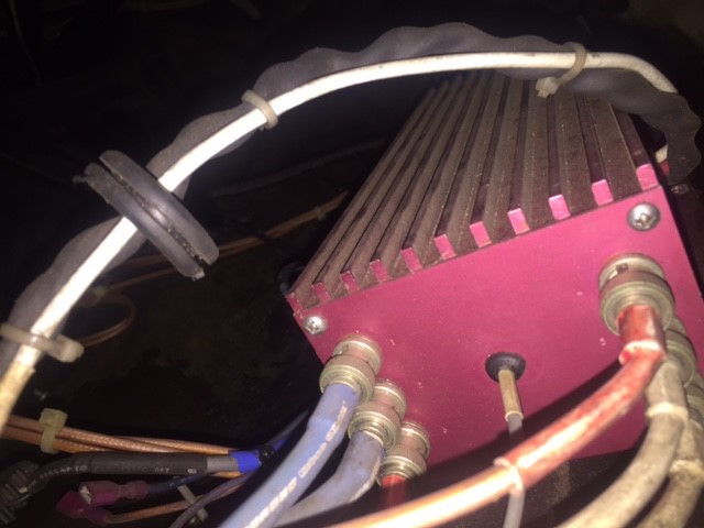
|
||
|
05-04-2018, 08:04 AM
|
|

|
|
It's a 914 ...
Join Date: Jan 2008
Location: Ossining, NY
Posts: 4,809
|
Sorry for the delay posting the manual! See below. Manual first, and a supplement in the next post.
Re: the trigger, the manual references a Hall effect trigger. Are you sure yours is a mag sensor? Scott        
|
||
|
05-04-2018, 08:39 AM
|
|
|
It's a 914 ...
Join Date: Jan 2008
Location: Ossining, NY
Posts: 4,809
|
And the supplement ...
   
|
||
|
05-04-2018, 08:41 AM
|
|
|
Registered User
Join Date: Feb 2017
Posts: 49
|
THANK YOU ALL SO MUCH - this is literally saving me - trying to get to a race and this component is the last thing I have to tie together - Scott, I greatly appreciate you taking the time to post that. It is just like the picture - at the bottom right of the diagram - so it is most likely just as diagramed. this is AWESOME - thank you all again!!!!!!
|
||
|
05-04-2018, 08:59 AM
|
|
|
Registered User
Join Date: Feb 2017
Posts: 49
|
Scott and Fred,
On the diagram and what Fred typed, the coils are on each side of the engine bay. If a coil has 1/4, as per Fred, it would fire plug 1 and 4 (1 at TDC, 4 at BDC). On a dual plug setup, why would you just not put the two coil output plug wires to the top and bottom of cylinder 1? Does the ECI only fire the top of coil 1 and the top of coil 4? I would think if, just for example), coil 1 is going to cylinder 1 and the ignition spark fires both top coil outlet and bottom coil outlet of coil 1, wouldn't it be easier to just put the two plug wires to the top and bottom of the head for cylinder 1? Am I messing something up in my thinking here?
|
||
|
05-04-2018, 11:10 AM
|
|
|
Registered
|
Firing arrangement..........
Quote:
Edit: I just read the posted manual pages. At the bottom of the last page under "Operation", it states that this is a wasted spark system, thus the 1/4, 2/5, etc are correct. So, with this design and the way the coils are mounted, the plug wires will have to cross the engine. You can minimize this by mounting the coils on the little shelf between the rear seat and the engine like I did. The wires will still have to crisscross but at least they will be neater and out of the way! The instructions also say to mount the control box in a cool spot and I put the control box for my system on the little flatspot just below the passenger side rear seat. Moving things around is much easier to do while the engine is out of the car! So, it looks like you now have enough info to make this one work, or you can shell out about $1300 for an Electromotive system!
__________________
FEC3 1980 911SC coupe "Zeus" 3.3SS god of thunder and lightning Last edited by fred cook; 05-04-2018 at 11:31 AM.. |
||
|
05-04-2018, 11:15 AM
|
|
|
Registered
|
Pictures of my car............
Just found some pictures of the coil and control box as installed in my SC. Might give you some ideas!
Ignition coils on shelf, mounted on bracket made from steel angle.  Unit control box mounted inside the cabin. 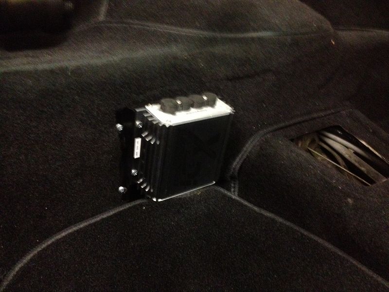
__________________
FEC3 1980 911SC coupe "Zeus" 3.3SS god of thunder and lightning |
||
|
05-04-2018, 11:39 AM
|
|
|
Registered User
Join Date: Feb 2017
Posts: 49
|
Thanks Fred - from all that I was reading and all that I could research, it did seem to me that you would be sending wires across the engine (the previous owner had a wire diagram but no manual etc). That is the main reason for my inquiry - the way he had the plug wires was like the first scenario. Very short, one coil to one cylinder top and bottom. So the coils were labeled like the wasted spark system, but "plumbed" like the first scenario. Very confusing - don't know if previous owner changed something, just did it wrong whatever. In addition, the coils lineup is different than you spoke about - you can see that in the picture. Thanks so much for all the time and help.
|
||
|
05-04-2018, 11:48 AM
|
|
|
Registered User
Join Date: Feb 2017
Posts: 49
|
Scott, are you running dual plug - would
you be able to shoot a picture of your setup - coils/control box and wires?
|
||
|
05-04-2018, 12:57 PM
|
|


 Zeus (god of thunder and lightning)
