|
|
|
|
|
| Author |
|
|
Registered
Join Date: May 2004
Location: Boulder, Colorado
Posts: 7,275
|
Andrew - in the class I race my '82 US SC (well, that is what the engine and transmission ratios are) in, the air filter is free. The exhaust from port to tail pipe is free. I can set the stock cam wherever I want, and the stock distributor where I want. And adjust the CIS how I want, but not replace it or a key part (like the WUR). I can use high strength rod bolts. But basically the engine's parts have to be stock.
I've got the Henderson/Buckley exhaust. Loud as hell, but at least 10hp better than what Porsche used on those cars in the day, or the '74 headers or SSIs, etc. After doing all my engine assembling and tuning for years I paid, as a present to my wife so she could race it for a year a shop with winning cars to do a rebuild, and it set the cams (I had set them mid range per Bruce Anderson) and distributor timing - which has to deal with our pump fuels. The shop owner then test drove it to match a track record even though he was too tall for the fixed seat and didn't try to see what more he could do. The car has more potential than I have as a driver (I'd like to think not much on some tracks, but on others I can see I am way off the best). I can't imagine that running as rich as it does at WOT isn't giving away something. Why would Bosch publish those nice graphs of AFR vs power, economy, and NOx if AFR at WOT didn't matter. |
||
 08-06-2020, 04:59 PM
|
|
|
El Duderino

|
Walt, I think what you’re getting at is that if max power is ~12 and you’re getting to 10s, have you gone past the point of diminishing return and now you’re in fact getting LESS power?
That’s a fair question and the reason I was asking about time interval. If you’re in the max power band on the straightaways then I tend to think don’t be concerned if you blip up to 10s when you let off the gas (for example). But if you’re consistently in the 10s on the straightaways then what is the net result?
__________________
There are those who call me... Tim '83 911 SC 3.0 coupe (NA) You can't buy happiness, but you can buy car parts which is kind of the same thing. |
||
|
08-07-2020, 12:28 PM
|
|
|
Registered
Join Date: May 2004
Location: Boulder, Colorado
Posts: 7,275
|
Best I can tell, the only fairly stable readings are a) idle, and b) WOT accelerating down a straight, maybe can tell upshifts by spikes. One reason I believe this is that I look (occasionally) at the reading while on the straight. In an SC, on the long Brainerd straight where I have hit 130 (not this year) before turning in (no braking for T1 in a car which only hits this kind of speed), there are 2 upshifts (3d to 4th, and 4th to 5th, and plenty of time to glance at instruments if you aren't catching someone (the norm is for 991 RSRs or GTB cars to blast past). Not so beyond that.
And those are the over rich readings - what I see with my foot to the floor. So they have to correlate with what I see on the graph of what is recorded by the LM2. When I get around to screen copying bits of the recordings I'll post. For checking the frequency system I added a BNC connector to the Acceleration Enrichment unit, so can read on a scope. Alas, since this is PWM, I can't just put a frequency counter on it. Easy enough to spot 50%. As long as 65% is the only other value (O2 sensor not hooked up) anything different would be the 65%? I have a dwell meter, though it is old, was cheap, and I've been a bit unsure about trusting it. I think this is what I was seeing three years ago when I was heavy into fiddling, opened up the "ECU", added wires, etc. If I get really creative, my LM2 has several data inputs for 5V signals. I'd have to go back to the drawing board on that, refresh recollection of what the voltage level involved with the FV is, etc. If it is 12VDC peak to peak, maybe a simple resistive voltage divider would knock that down to 5? That would provide a FV trace on the Innovate graph. Might help identify where I was off the gas braking, show the (brief) time the throttle was in the cruise segment of its travel (trail brake?), etc. But without the O2 sensor telling the system what to do about the pulse width, and then only at the cruise range of the throttle switch, I'm not sure what monitoring this will do for me. I know the switch works, and the FV responds as it is supposed to based on that switch. How is this going to help me get the WOT AFRs to a better place? The emissions screw alone has proved to me that it can't influence WOT enough to do this, pretty much no matter how lean I make it at idle. Plus I can see why that screw is less effective as the air flow gets up into the WOT range. Hence the hunt for some other way without adding electronic stuff. Last edited by Walt Fricke; 08-07-2020 at 05:40 PM.. |
||
|
08-07-2020, 05:38 PM
|
|
|
Registered
Join Date: May 2004
Location: Boulder, Colorado
Posts: 7,275
|
I mistakenly posted some verbiage and pictures at this location, thinking it was this topic. It was on CIS, but a guys problems. Take a look.
Engine stalling off of acceleration Here is what Porsche had to say about the effects of the three wire throttle switch:   I see I was wrong about the sensor having no effect at idle. In a warm engine it does, but thats not what I care about. This seems to confirm that closed loop has no effect on warm (which is all track guys care about) WOT AFM. Any counter argument? Andrew estimates that a 55% duty cycle at WOT open loop would give AFMs in the desired high 12/low 13 range. How might one go about doing that without just replacing the ECU (or its innards)? To start with, assume no O2 sensor, so the base is 50% idle, 50% cruise, and 65% WOT. The 3 wire throttle switch could be used to disable the WOT duty cycle, which would remain at 50%. I suppose I could try that. I'd have to have the function of the 3 way switch right. Here is what I think it does in this regard: at warm idle or cruise (throttle below 35*) it is open. At WOT it is closed, and provides a ground to pin 7 on the ECU. Leaving the thermostat connection to pin 7 (opens at 15*C) alone, disconnect ECU pin 7. Check to see if WOT is 50%. If this works, I see two likely alternatives, both using the WOT closure of this part of the throttle switch: A) provide the O2 sensor input to the ECU (pin 2) a dummy 02 signal. Should be easy to provide a signal which varies at a frequency between 0.1V and 0.9V which will do the trick. I haven't figured out what that might be, though. The FV frequency is 70 Hz (or 69). But it is the on pulse width for that set frequency (which is generated in the ECU) which controls the pulse width modulation to the FV. So that is question 1: what fake 02 signal would cause a 55% (or some other, based on dyno testing) duty cycle at WOT. B) directly drive the FV. The same WOT switch would provide the ground to a relay controlling power to a pulse width generator set to 55% at 70Hz. To be safe maybe, the same relay could disable the signal doing this generated in the ECU and sent from pin 15. This would require figuring out what the signal voltage should be, and its current capacity. Here is the tricky bit: The scope signals from the test pin on the ECU (pin 17, also found at the test plug in the engine bay) are nice square waves of about 6 volts peak to peak. Circuitry in the ECU must shape up the signal sent to the FV to make it look this nice. The scope picture of the signal from pin 15 to the FV, which is what turns it on and off, is much more complicated. In fact, I don't understand it beyond suspecting that the current needed to operate the FV is high enough to cause a big voltage spike, and maybe some of the rest of the form. Here is a CRT picture of what the two signals, taken on separate channels, looks like. Also one of my digital scope pictures of the same thing.   And another CRT:  Plus what someone posted as what powering a fuel injector on and off looks like: 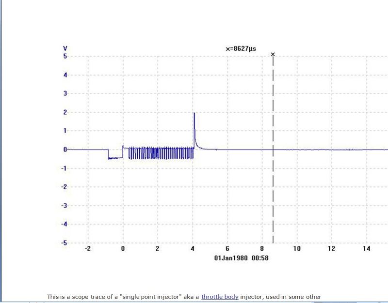 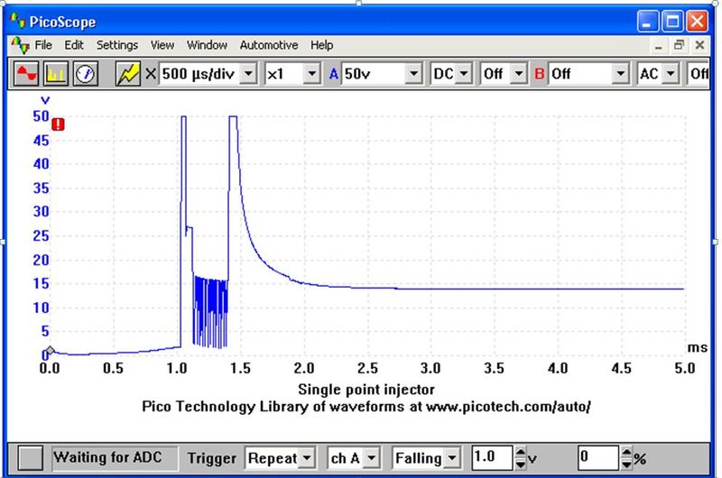 So question 2 is what specs do I need for a PWM generator set at a frequency of 70Hz and a duty cycle of 55%? Can I accomplish that with a 555? I've got a handful of those and the resistors and capacitors needed to control things (would need help figuring out values, though). Or something else? Walt |
||
|
08-09-2020, 04:52 PM
|
|
|
Registered
Join Date: May 2004
Location: Boulder, Colorado
Posts: 7,275
|
Control Unit Accelleration Enrichment unit
The 81-3 US 3.0 CIS system has an additional electronic component in a cigarette sized pacage, attached next to the large ECU: The "control unit accelleration enrichment" box, which shows up on the wiring schematic for these models. What does it do? Looking at the Porsche or Bosch information on what throttle position has to do with fuel enrichment finally led me to understand its function. If I have doped it out right, when the throttle goes from idle, or just above 1 degree of opening (micro switch opens) and the engine is cold (maybe also warm, but not at operating temperature), there is a 2 second burst of a 75% duty cycle to the FV.
This must have been a useful add-on to deal with sluggish response on cold engines, maybe merely warm engines, when getting going headed out on the Autobahn. Rather than redesign the PCB of the ECU for this, Bosch just added another box. Sort of like how all the throttle air systems got added to the pre-ECU CIS. So it would appear that this CUAE box is irrelevant for track driving, where your engine is always hot after the grid and a warm-up lap or formation lap. Have I got this right? Ignoring this box when it comes to thinking about WOT AFRs simplifies things. |
||
|
08-09-2020, 05:05 PM
|
|
|
Registered
Join Date: May 2004
Location: Boulder, Colorado
Posts: 7,275
|
LM2 graph traces
  About 2 minutes, which is about one lap, at Brainerd. Idling on grid, then driving through hot pit to track. |
||
|
08-09-2020, 05:16 PM
|
|

|
|
Registered
|
Quote:
Means: When driving normal and the working lambda control shows a duty cycle of 20% (which is normal when driving at i.E. 2000-3000 RpM) which in this state is needed for Lambda 1 (14.7:1 AFR), then a jump up to 65% when accel., like the original ECU does, will result far off an AFR of 12.5:1! See the point? Thats the very downside of the original ECU that the control actually switches to a static 65% duty cycle when accelerating. But in that generation of ECU where simple electronic components are included, no conditional programming was possible to just "add" a value of duty cycle percentage for a proper 12.5:1 resulting mixture. And thats what I meant: IF the ECU let the duty cycle result in 30% for hitting Lambda 1 when driving normal, then a duty cycle of 55% would result más o menos in Lambda 0.85, means an AFR of 12.5:1. So th 55% example above is not a static value where this will give a proper 12.5:1 at all RpMs/conditions.
__________________
911 SC 3.0, 1982, black, US model with own digital CPU based lambda ECU build and digital MAP based ignition control All you need to know about the 930/16 and 930/07 Lamba based 911 SC US models: https://nineelevenheaven.wordpress.com/english/ |
||
|
08-10-2020, 01:31 AM
|
|
|
Registered
|
Quote:
If the initial CO screw setup meets the factory specs, means a CO of approx. 0.6% with unplugged sensor and a hot engine, then when sensor is plugged again, a resulting duty cycle is in the up to 60% range. So ... if engine is cold and by this the lambda operation is switched off, then the cold duty cycle of 65% would be not enough for a jerky free slight accelrating out of a cold idle. Thats why the unit pulls the duty cycle to 75% at 5° throttle angle and at 15° angle as well. And this at both states, means when deaccel. and accel.
__________________
911 SC 3.0, 1982, black, US model with own digital CPU based lambda ECU build and digital MAP based ignition control All you need to know about the 930/16 and 930/07 Lamba based 911 SC US models: https://nineelevenheaven.wordpress.com/english/ |
||
|
08-10-2020, 01:42 AM
|
|
|
Registered
|
Quote:
__________________
911 SC 3.0, 1982, black, US model with own digital CPU based lambda ECU build and digital MAP based ignition control All you need to know about the 930/16 and 930/07 Lamba based 911 SC US models: https://nineelevenheaven.wordpress.com/english/ |
||
|
08-10-2020, 01:42 AM
|
|
|
Registered
Join Date: May 2004
Location: Boulder, Colorado
Posts: 7,275
|
AFR scale on left. Top is roughly a lap on the track racing, maybe 1st or 2d lap after the start (I should capture one much later in the race, I suppose). Scale in the middle is time from start in minutes and seconds (snip for bottom graph didn't get time ticks, but same) at 2.5 seconds per gradation. Bottom is idling on grid, then modest driving through hot pit to get to track. Both about 2 minutes.
I assume lean spikes are braking and upshifting, where off the gas. Braking only 6 times per lap, with one lift. One upshift from 3 to 4 and 5 on a long straight, one from 3 to 4. One downshift from 5 to 3 (I don't go through 4), one from 4 to 3. |
||
|
08-10-2020, 12:30 PM
|
|
|
Registered
Join Date: May 2004
Location: Boulder, Colorado
Posts: 7,275
|
Innovate has an RPM channel, a voltage channel, and several other, undedicated channels. The RPM channel can give spotty results - you are advised to use a potentiometer as a voltage divider to calm the RPM signal down. Sometimes I believe the results, sometimes they have the RPMs way high - I know what my upshift RPMs are from the tach. I used another of the channels to record control pressure on the track, but didn't learn anything significant before the sensor for some reason quit three years ago. The guy behind Innovate knows his electronics and programming, but his documentation can be somewhat over the head of someone like me who knows the concepts, but hasn't internalized the steps needed. Plus he got tired of answering questions (engineers who write manuals tend to be irritated by people who didn't seem to read the manual), so I haven't been able to get much help there. And, having just bought another wide band sensor from Innovate, I suspect maybe the Holley etc carburetor company may have bought him out?
|
||
|
08-10-2020, 12:44 PM
|
|
|
Registered
Join Date: May 2004
Location: Boulder, Colorado
Posts: 7,275
|
Andrew - there is very little part throttle on a race track. WOT, upshift, WOT, brake/throttle closed, WOT. Smooth acceleration often means you squeeze back on the gas a bit before the apex, or at it, or a bit after, maybe reaching WOT at about track out, though sometimes by the apex. But mostly foot to the floor, or idle. Plus the blip for downshifting to match RPMs.
|
||
|
08-10-2020, 01:57 PM
|
|

|
|
Registered
|
Quote:
Quote:
__________________
911 SC 3.0, 1982, black, US model with own digital CPU based lambda ECU build and digital MAP based ignition control All you need to know about the 930/16 and 930/07 Lamba based 911 SC US models: https://nineelevenheaven.wordpress.com/english/ |
||
|
08-10-2020, 02:35 PM
|
|
|
Registered
Join Date: Nov 2017
Location: Houston, TX
Posts: 870
|
Quote:
What does the CIS do when throttle is closed? Presumably it thinks the engine is idling, and therefore provides the idling quantity of fuel? If so, those lean spikes make some sense. Does not explain super lean idle, is that on purpose, Walt? Sent from my Nokia 7.1 using Tapatalk Last edited by Mixed76; 08-10-2020 at 02:46 PM.. |
||
|
08-10-2020, 02:44 PM
|
|
|
Registered
Join Date: May 2004
Location: Boulder, Colorado
Posts: 7,275
|
1) The Innovate wide band sensor is in the bung in the left side exhaust after the collector. So no Lambda system adjustment.
2) The very lean idle is from trying to get WOT to go leaner (stop being so rich) and be at or closer to the AFR for max power. I think it nudged the WOT readings up some, but not there from what I see looking at the display on the straights when not otherwise occupied. 3) Porsche/Bosch built in a system to deal with what happens when you snap your foot off the gas. I think the center gizmo in the first picture does that, with the nipple connected to the throttle body below the butterfly, to provide a vacuum allowing unmetered air to lean out the mixture. The second photo shows where this air enters the rubber boot over on the left (the other tube in the boot is the breather tube for the oil tank).  
|
||
|
08-10-2020, 11:08 PM
|
|
|
Registered
|
Quote:
With lambda control deactivated and then reducing the CO value at idle in such a way to compensate an over enrichment at WOT is not the way. Thats why your mixture in your plot shown above leans out that much when deaccelerating. Just my two cents. I really suggest you should reactivate your lambda so you can exactly follow your approach you do above by using such a lean initial CO value, .. but then with lambda control at idle or deaccelerating your mixture won't lean out that much cause the ECU brings the mixture back to stoich. I have an innovate sensor/controller as well, ok a LC-2 but I guess yours also comes with an narrowband supporting 0-1v output (brown wire?) where you can try to connect this as sensor signal to the ECUs Pin2 (inner signal of the sealed green wire) terminal. In case of that the ECU won't support this signal, go into the innovate sensor setup using the software and try to change the signal setting from sensors initializing and failure state from "0v" to "high resistance".
__________________
911 SC 3.0, 1982, black, US model with own digital CPU based lambda ECU build and digital MAP based ignition control All you need to know about the 930/16 and 930/07 Lamba based 911 SC US models: https://nineelevenheaven.wordpress.com/english/ Last edited by AndrewCologne; 08-12-2020 at 06:47 AM.. |
||
|
08-12-2020, 03:46 AM
|
|
|
El Duderino
|
Quote:
There are other differences over the years and markets.
__________________
There are those who call me... Tim '83 911 SC 3.0 coupe (NA) You can't buy happiness, but you can buy car parts which is kind of the same thing. |
||
|
08-12-2020, 12:27 PM
|
|
|
El Duderino
|
Just a thought, but don’t these wideband sensors require a periodic re-calibration process?
__________________
There are those who call me... Tim '83 911 SC 3.0 coupe (NA) You can't buy happiness, but you can buy car parts which is kind of the same thing. |
||
|
08-12-2020, 12:32 PM
|
|
|
Registered
|
The manual of the LC-2 wideband controller i.E. gives here recommendations for the calibration intervals.
At the beginning I re-calibrated all 6 months, but here no change, so I increased the interval to every year – but lets see, I'm quite shure there will be no need to do the job in an interval less than every two years
__________________
911 SC 3.0, 1982, black, US model with own digital CPU based lambda ECU build and digital MAP based ignition control All you need to know about the 930/16 and 930/07 Lamba based 911 SC US models: https://nineelevenheaven.wordpress.com/english/ Last edited by AndrewCologne; 08-13-2020 at 01:17 AM.. |
||
|
08-13-2020, 01:13 AM
|
|
|
I am my 911's PO

|
Walt,
Are we ready for an off the wall comment?  Have you considered forcing the Lambda system to run in Mode 1 by grounding the 15C switch? Compared to the table in your post #6, that will cause the FV to cycle at 65% across the board, unlike the Mode 3 operation that has the FV duty cycle at 50% at idle and 65% (richer) at WOT. Note there will still be brief enrichment (75% duty cycle) when coming off idle. That would give a starting point where both idle and WOT AFR are low, so there's room to lean out the mixture across the RPM range by increasing the WUR warm pressure (maybe even staying within high end of spec). Using that and the idle mixture might get where you want to be at WOT and have an acceptable idle AFR. All this would make cold starts (actual cold weather starting) difficult if not impossible, but I understand your priorities for a track car. Last edited by '78 SC; 08-13-2020 at 02:36 PM.. Reason: clarify cold start |
||
|
08-13-2020, 09:14 AM
|
|


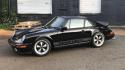 1983 Porsche 911SC Coupe
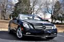 2011 Mercedes-Benz E350 Cabriolet
 Volkswagen Bug - Split window
 Porsche 911
 Volkswagen Bug - Oval window
 street car
 tow vehicle
 track car
