|
|
|
|
|
| Author |
|
|
Registered
Join Date: Dec 2002
Location: So Cal and So Oregon
Posts: 2,211
|
Updating most of the electrical system - an experiment
I just finished successfully stripping some unused systems from my car in my effort to simplify it and make it more reliable. I documented some of that here:
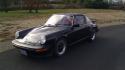
so this is how a backdate project starts... and more specific to the electrical, here: battery relocate = fuse box relocate? A few people have asked for more information, so I thought I would step back and describe my approach. I have owned the car (a 1985 Targa) since 1989 and put 250,000 miles on it. The systems that started failing were the A/C, warning system, and auto heat. In addition, I wanted to remove the cruise control, fog lights, interior lighting, radio, cigarette lighter, power mirrors, and to backdate the heat. I wanted to replace the jumble of wires and old fuses with a newer simpler, cleaner approach. In the original Porsche scheme, the power for much of the systems is run through the ignition switch and from there to the fuse panel based on the key position in the switch. that switch acts as the power distribution point. It also feeds the power to the light switch from which most of the lighting was powered. To me that was asking a lot of two switches. I decided that, rather than run power through the ignition and light switches, I would distribute power through electrical busses and relays. Last edited by SpyderMike; 04-08-2015 at 09:13 AM.. |
||
 04-07-2015, 06:23 PM
|
|
|
Registered
Join Date: Dec 2002
Location: So Cal and So Oregon
Posts: 2,211
|
The first thing I did was to identify key locations in the frunk. I wanted to identify every wire, where it was coming from and where it was going to and its function. I identified these locations as the Headlight Bundle (the looms coming in from the left hand front headlight area), the Penetration Up-front Near the Brake Booster (PUNB) from which the looms head down into the area in front of the pedal cluster, the Under Near Dash area (the area in the frunk where the rats nest is near the gauges), and the Battery + terminal area.
I then started to take the fuse box apart. As I removed each wire, going from the rear of the fuse panel to the front, I labeled it counting the connection point from back to front 1T for 1 Top, 1B for 1 Bottom, etc. This does not align to the fuse designation as fuse panels are (from back to front) 3, then 1, then 2. Note that 5T and 5B might not relate to the same fuse as there are more connection points on top than bottom. This may not be the smartest way to go - it may make more sense to relate and label the connections to the proper fuse from the beginning (e.g., Fuse 1-3Top). I later related these connection points to the proper fuse locations in a spreadsheet you can view below. Last edited by SpyderMike; 04-08-2015 at 09:14 AM.. |
||
|
04-07-2015, 06:23 PM
|
|
|
Registered
Join Date: Dec 2002
Location: So Cal and So Oregon
Posts: 2,211
|
As I undressed each loom, I made sure that the individual looms were numbered so that I could keep track of what wires were bundled together. I wrote down each relative wire gauge (S, M, M/L, L), the base color of the wire and the strip color. I undressed all of the looms while trying to keep each of them loosely intact using tie wraps. After getting them all undone, I identified the obvious wire looms that I could get rid of and pulled them out. Whenever I had to cut a wire to get it out of the way so that I could extract a loom, I labeled each of the resulting cut ends. Before I cut any wire, I double/triple checked its function.
The next step was to try to untangle the rats nests and have the wires take logical paths. This was an effort to try to clean the mess up. I tried to group by function and destination. I realized at this point that some wires were much too long and that I would splice them down. I had to learn more about the systems and how they work so that I could do this properly. This took the most time - studying schematics. I prefer the Bentley for functional description, and the Haynes for physical representation. |
||
|
04-07-2015, 06:24 PM
|
|
|
Registered
Join Date: Dec 2002
Location: So Cal and So Oregon
Posts: 2,211
|
I relocated an Oddessey PC680 battery to the smugglers box. Next to it I installed a continuous duty battery contactor. The contactor acts like a big relay to power an electrical bus. This is how they tend to wire airplanes and mimics the airplane I am building. The main fuse box would be right behind the smugglers box where the fresh air fan assembly was. I chose a Bussman Cooper ATO type of fuse block P/N 15713-24-12-22A (Waytek Wire - less than $45) containing three busses. One was to be the Always Hot Buss tied to the battery, one was to be the Contactor fed buss which would be energized when the key switch is in the Run and Start positions, and one was to be energized when the light switch was engaged (I ended up not using this as it would mean extending wires from the left fender area back to this fuse panel and I elected instead to mount a remote fuse block at the fender area).
The three secondary fuse blocks would be at the location of the original fuse panel on the left hand fender. I used ATO type modular blocks Del City 73895 (Amazon - less than $5 each). There would be one fuse block for the turn signals (one fuse for each corner of the car), one fuse block for the Other Lights that light up when you pull the light switch (gauge lights, license plate lights, park lights left, park lights right), and one fuse block for the headlights (one fuse each for high beam and low beam on each side). Last edited by SpyderMike; 04-08-2015 at 09:18 AM.. |
||
|
04-07-2015, 06:25 PM
|
|
|
Registered
Join Date: Dec 2002
Location: So Cal and So Oregon
Posts: 2,211
|
There are five new style relays in this scheme. I used a modular Relay group Genssi 40AMP-HRNS (Amazon - less than $15 for five) for the relays in the frunk, and the Hot Start Relay kit from Pelican at the back.
The first is triggered when you pull the headlight switch out and it powers the Other Lights fuse block. I used the gray wire coming from the light switch position K as the power trigger to engage this relay. I ran a single large gauge power feed from the RS Buss of the main fuse block to this relay. The second relay powers the High Beam headlight circuit. I used the white wire that used to send power from the light switch to the high beams to trigger this relay. The third relay powers the Low Beam headlight circuit. I used the yellow wire that used to send power from the light switch to the high beams to trigger this relay. Both the High Beam and Low Beam relays have a single shared power feed (because only one or the other will be active at any one time) from the main fuse panel. Each of the first three relay grounds were taken to single grounding point at the front left corner of the frunk. The fourth relay powers the Horn circuit. Here I used the small gauge brown/white wire that grounds when you push the horn button as the ground for the relay. A single large gauge wire from the main fuse panel is used as the power feed and is jumpered to the trigger feed of the relay. The fifth relay is referred to as a Hot Start Relay and it is located near the starter. Originally, a larger gauge yellow wire from the ignition switch winds its way back to the starter and sends power to engage the starter when the ignition key is turned to the start position. Now that yellow wire carries much smaller current and triggers the local Hot Start Relay. This relay gets its main power feed locally at the starter from the large gauge main feed from the battery. I continue to use the original Hazard/Turn Signal relay and Power Window relays. Last edited by SpyderMike; 04-08-2015 at 09:19 AM.. |
||
|
04-07-2015, 06:25 PM
|
|
|
Registered
Join Date: Dec 2002
Location: So Cal and So Oregon
Posts: 2,211
|
I had to find a way to trigger the battery contactor. It needs a switched ground to trigger. I realized that I could use the outside mirror selector switch for this purpose. This would make a nice discrete way to prevent theft too as the switch handy, but is barely noticeable. I ran one wire to the contactor trigger and the other to a collective ground in the Under Near Dash area.
Next I came up with a fuse scheme and it will be found further below because I can not edit to add a picture. I ran the wires to the applicable fuse blocks and cut them to length (but slightly long). I used crimp terminals like this and the proper crimp tool. I then soldered each connection and covered the crimp/solder area with heatshrink. Last edited by SpyderMike; 04-07-2015 at 06:33 PM.. |
||
|
04-07-2015, 06:26 PM
|
|

|
|
Registered
Join Date: Dec 2002
Location: So Cal and So Oregon
Posts: 2,211
|
I know I did this next step too soon. I used this tape - Tesa Black High Heat Cloth Tape (Amazon - about $13 a roll - one roll) to dress each logically grouped loom. Eventually, I had to make adjustments when I found error in my thinking and I had to undo a few looms and regroup. It was a pain. I should have continued to group using tie wraps and kept them like that until done.
When it was all done, I installed the positive battery terminal first and then the negative terminal. No smoke! I then tried the battery contactor trigger and could hear it engage. Still no smoke. I then de-energized the contactor and plugged fuses in one-by-one for the Always Hot buss while looking for issues. I found none. I then plugged in one-by-one the fuses for the Run/Start Buss and energized that buss after each was installed to see if I had issues. Once I had fuses powering a particular function, I tested that function to make sure it worked properly. Lastly, I fused the remote blocks in a similar manner. Everything worked as it should. |
||
|
04-07-2015, 06:27 PM
|
|
|
Registered
Join Date: Dec 2002
Location: So Cal and So Oregon
Posts: 2,211
|
So this is now how it works, I engage the Run/Start contactor by flipping the mirror selector switch at which point the gauges come alive and the battery light turns on letting me know the buss is alive. I then start the car as normal. I have to shut down by turning off the key and then switching the mirror selector off - I see the battery light extinguish.
Was it worth it? I feel a lot better having all the non-functioning circuits and the associated wiring out. I pulled some 100 pounds out of the car. I weighed the wiring I removed and it came out to 15 pounds. More than that, I really understand the electrical systems in the car now. |
||
|
04-07-2015, 06:27 PM
|
|
|
Registered
Join Date: Dec 2002
Location: So Cal and So Oregon
Posts: 2,211
|
So here is the fuse list:
 Here is the simple soldering station setup (less than $50 for everything):  The other essential tools (cutter, stripper, crimper):  The contacts the fuse blocks used:  The heat gun (Amazon - less than $20) - a hairdryer might work instead:  The assorted heatshrink kit (Auto Part Store - $11):  And the fuse kit (auto parts store - $12): 
|
||
|
04-07-2015, 06:39 PM
|
|
|
Registered
Join Date: Dec 2002
Location: So Cal and So Oregon
Posts: 2,211
|
And here is the result:
     Not the prettiest, but functional and reliable. I still need to label the relays and fuse blocks. I will upload my wiring connections spreadsheet once I figure out how. |
||
|
04-07-2015, 06:50 PM
|
|
|
Registered
Join Date: Dec 2002
Location: So Cal and So Oregon
Posts: 2,211
|
Here is my connections list:
 
|
||
|
04-07-2015, 07:08 PM
|
|
|
Registered
Join Date: Mar 2010
Location: New England
Posts: 257
|
Great write up! I have been going back and forth debating whether to do this to my 85 coupe for a while. About 18 months ago I had a pretty large electrical short in the instrument cluster which cooked a large portion of the dash harness. I had someone rewire a lot of it, but with mixed results. and now I have a few nuisance issues that I think the only way to exorcise is to do what you've outlined here.
Thanks!!
__________________
- 85 Carrera - |
||
|
04-07-2015, 07:39 PM
|
|

|
|
Registered
Join Date: Dec 2002
Location: So Cal and So Oregon
Posts: 2,211
|
You are welcome. I noticed some browned wires coming out of my ignition switch and light switch. I am glad I did this when I did.
Mike |
||
|
04-07-2015, 08:05 PM
|
|
|
Registered

Join Date: Aug 2008
Location: sectors R&N, SE Pa
Posts: 3,117
|
Quote:
You can definitely tell the difference since there are far fewer wires visible, and your write-up / approach make it sound cool and systematic. Nice job. I'm a sparky so I may be biased. :-)
__________________
Dan '87 Targa Carrera 3.2 - Fabspeed Cat Bypass, M&K Muffler, SW Chip Venetian Blue |
||
|
04-07-2015, 09:53 PM
|
|
|
ROW '78 911 Targa
|
Nice work stripping it to the basic functions. You definitely removed a lot of items..
Not sure if I'd trust that little mirror switch, I think I'd install a better toggle switch. Looks good and appears to meet all your needs.
__________________
Dennis Euro 1978 SC Targa, SSI's, Dansk 2/1, PMO ITBs, Electric A/C Need a New Wiring Harness? PM or e-mail me. Search for "harnesses" in the classifieds. |
||
|
04-07-2015, 11:01 PM
|
|
|
Registered
Join Date: Dec 2002
Location: So Cal and So Oregon
Posts: 2,211
|
Thanks Steely, I appreciate you comments.
I agree on the mirror switch Dennis. I will be moving the defog switch and possibly the light and hazard switches to another location once I redo the interior...I will probably replace it then. By the way, where are you in Salem. I was a South Salem Saxon class of 1977. Mike Last edited by SpyderMike; 04-08-2015 at 09:12 AM.. |
||
|
04-08-2015, 08:14 AM
|
|
|
Registered

|
Great write-up. I was talking to my wife yesterday and she suggested I could tackle a total re-wire sometime in the next year. My SC has 259K on it, and various things don't work - heater fan, power antenna, fog lights.
How long did it take? I am considering pulling all the wires and putting in new ones everywhere. I have experience in basic electronics. I've built a DC power supply and solder things occasionally.
__________________
Lillie - 1979 911 SC Targa, The Original 911 SCWDP Car. Rebuilt and roaring to go! |
||
|
04-08-2015, 08:28 AM
|
|
|
El Duderino

|
Mike,
I like your creative thinking! Good job! A friend of mine did a complete CAN bus system on a 260Z. It's all LED/HID lighting and Haltech EFI. I've wondered about how hard it would be to do something similar to a 911.
__________________
There are those who call me... Tim '83 911 SC 3.0 coupe (NA) You can't buy happiness, but you can buy car parts which is kind of the same thing. |
||
|
04-08-2015, 08:40 AM
|
|
|
ROW '78 911 Targa
|
Hi Mike.
West Salem. Keep us posted on the future changes, you have a very creative approach.  I've had a few people ask me to build stripped harnesses for them. They have kept the original fusing in place though. |
||
|
04-08-2015, 08:48 AM
|
|
|
Registered
Join Date: Dec 2002
Location: So Cal and So Oregon
Posts: 2,211
|
Nice, I have friends and family in West Salem. I am there about every other month.
I will be changing out the rear fuse block soon, but that should be a lot easier. I knew if I screwed this up that I could come to you for a replacement new harness. It was a nice safety net to have. I admire your work. Last edited by SpyderMike; 04-08-2015 at 09:02 AM.. |
||
|
04-08-2015, 08:54 AM
|
|


 Heinz
Heinz Lillie
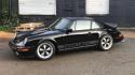 1983 Porsche 911SC Coupe
 2011 Mercedes-Benz E350 Cabriolet
