|
|
|
|
|
| Author |
|
|
Registered

Join Date: Aug 2002
Location: Camarillo, CA
Posts: 2,263
|
R1100S - 10mm Shortened Telelever
Just wanted to post my latest modification to my R1100S. I have been able to modify the stock telelever arm on the R1100S to the 10mm shorter specs that San Jose BMW and a couple others (shreddr and cageyar) have done to their R1200's. The results are fantastic on the old gal. Just as shreddr had been trying to tell ya'll, this is one fantastic mod for the R1100S as well.
I have had this mod in place for the past 4-5 months and have been taking my time to decide if it really made a difference worth mentioning. It has made all the difference in the world to this bike. The turn in on corners now is effortless. Before I always had to hike out far on the seat to be able to feel the corner entry, but now it just falls into place without much thought at all. The 1.2 shorter rake angle and 3/4" shorter wheelbase is exactly what these bike have needed from the very start. Anyone that is tired of trying to get their R1100S to handle like a modern sportbike should consider this modification. This is not exactly an easy mod for the average guy. It requires access to some good shop tools and welding equipment plus a lot of hands on skill. A few of you guys should be able to do it by yourselves and some others could hire someone to do it for you. It is definitely worth considering if you are getting the itch for a more modern handling bike. After doing this to my R1100S, I am totally in awe of it's handling and only hope I can keep it going way past the 70k miles I already have on it. If anyone is interested in giving this mod a try, I would be happy to share the details with you.
__________________
Scott '98 R1100S - Triple Clamps, 10mm Shortened Telelever 2013 KTM 990 SMT, 2008 KTM 990 SDR |
||
 07-28-2010, 07:45 PM
|
|
|
unsafe at any speed

Join Date: Dec 2003
Location: Arkansas
Posts: 12,357
|
Did you take pics???
__________________
Bill Swartzwelder 2002 R1100S Prep/ 2024 Tenere 700 |
||
|
07-28-2010, 08:08 PM
|
|
|
Registered
Join Date: Aug 2002
Location: Camarillo, CA
Posts: 2,263
|
Bill, no I did not think of taking pics at the time I did the work, but I modeled all the details on the computer and put together the procedure on a Word document. I can send it to you if you PM me your email address. I may post it here later if there is enough interest, but I was hoping for your input first anyway. You are definitely one of the "few" guys I was referring to when I was thinking someone may be interested in taking on this task.
__________________
Scott '98 R1100S - Triple Clamps, 10mm Shortened Telelever 2013 KTM 990 SMT, 2008 KTM 990 SDR |
||
|
07-28-2010, 08:29 PM
|
|
|
unsafe at any speed
Join Date: Dec 2003
Location: Arkansas
Posts: 12,357
|
My S is due for some lovin this winter.... I may give her a facelift too.
__________________
Bill Swartzwelder 2002 R1100S Prep/ 2024 Tenere 700 Last edited by wswartzwel; 07-28-2010 at 09:03 PM.. |
||
|
07-28-2010, 08:36 PM
|
|
|
Registered
Join Date: Aug 2002
Location: Camarillo, CA
Posts: 2,263
|
message on its way. This mod took me a couple days being very carefull. This will make any facelift justified, trust me.
__________________
Scott '98 R1100S - Triple Clamps, 10mm Shortened Telelever 2013 KTM 990 SMT, 2008 KTM 990 SDR |
||
|
07-28-2010, 08:51 PM
|
|
|
Registered

Join Date: Jun 2004
Location: Eastern Rockies
Posts: 1,796
|
Scott, how ya doin'?
I'd like to get a copy, too, if that's alright. PM'd an address if you don't already have it. thanks,
__________________
tm (R12, R11, R1) + 00 then S, S, /7 |
||
|
07-28-2010, 08:53 PM
|
|

|
|
unsafe at any speed
Join Date: Dec 2003
Location: Arkansas
Posts: 12,357
|
I am running one of those shorter billet paralever arms from Pirates Lair... Is yours stock? Do you have a shortened rear arm too. Just wondering if your mod will work well in conjunction with the raised up rear end.
__________________
Bill Swartzwelder 2002 R1100S Prep/ 2024 Tenere 700 |
||
|
07-28-2010, 09:03 PM
|
|
|
Registered
Join Date: Aug 2002
Location: Camarillo, CA
Posts: 2,263
|
Bill, I have been running a GS torque arm, 6" rear wheel, Ohlins shocks jacked up in the rear, meyoyo clamps. The beauty of this telelever mod is that you can run a lower rear height and still get incredible turning response. The result is a lower roll center and easier turn in. All good stuff.
__________________
Scott '98 R1100S - Triple Clamps, 10mm Shortened Telelever 2013 KTM 990 SMT, 2008 KTM 990 SDR |
||
|
07-28-2010, 09:11 PM
|
|
|
Registered
Join Date: Aug 2002
Location: Camarillo, CA
Posts: 2,263
|
Tony, PM'd ya.
__________________
Scott '98 R1100S - Triple Clamps, 10mm Shortened Telelever 2013 KTM 990 SMT, 2008 KTM 990 SDR |
||
|
07-28-2010, 09:12 PM
|
|
|
Registered
Join Date: Apr 2000
Location: Birmingham England
Posts: 3,396
|
Hi Scott
How are you!!,had your mod PM'd to me a while back via another site,top of my list for next winter,my wife will be happy if i can lower the seat height  And the clamps are as good as ever  Chris |
||
|
07-29-2010, 12:27 AM
|
|
|
Registered
Join Date: Aug 2002
Location: Camarillo, CA
Posts: 2,263
|
Chris, yes you got the first long winded version of the mod before anyone else. Give it a thought or two and dive in when you have a chance. Absolutely nothing to lose unless you mess up the mod. Just be careful and all will be good. I am counting on you for some UK input for all the rest of your guys.
__________________
Scott '98 R1100S - Triple Clamps, 10mm Shortened Telelever 2013 KTM 990 SMT, 2008 KTM 990 SDR |
||
|
07-29-2010, 12:43 AM
|
|
|
Registered
Join Date: Jul 2010
Posts: 7
|
Jeff Gill
Hi Scott, great to hear about your front end mod, I thought I just had to live with that turn in problem, put up with it for 100,000 K's, how do I go about getting info from you, I'am pretty new to this forum stuff, regards Jeff
|
||
|
07-29-2010, 01:17 AM
|
|

|
|
Registered
Join Date: Dec 2003
Location: Albany, GA
Posts: 4,574
|
I would like a copy too.
jerry.duke@gmail.com |
||
|
07-29-2010, 06:01 AM
|
|
|
Registered
Join Date: Apr 2006
Posts: 11,161
|
Hi Scott. Did you pattern your mod after Joe the Viking's HP2Sport trailing arm mod. He posted photos of the process.
http://forums.pelicanparts.com/bmw-r1100s-r1200s-tech-forum/466163-hp2-sport-telelerver-arm-mod-2.html |
||
|
07-29-2010, 06:18 AM
|
|
|
Registered
Join Date: Apr 2006
Posts: 11,161
|
Quote:
|
||
|
07-29-2010, 06:21 AM
|
|
|
Registered
Join Date: Dec 2003
Location: Albany, GA
Posts: 4,574
|
If the S doesn't sell, I might turn it into a track bike. Quickening the steering would be great.
|
||
|
07-29-2010, 06:40 AM
|
|
|
Registered
Join Date: Apr 2006
Posts: 11,161
|
Quote:
Well, that's a switch. Selling is a matter of price.
|
||
|
07-29-2010, 06:43 AM
|
|
|
Registered
Join Date: Aug 2002
Location: Camarillo, CA
Posts: 2,263
|
Bubba, I only used the 10mm offset as a reference in modifying the R1100S telelever. Unfortunately there is no direct swap to accomplish this. The stock telelever needs to be cut and welded. I tried to copy and paste the procedure here but it was too long. I'll see if I can shorten it or make two posts for all to see.
__________________
Scott '98 R1100S - Triple Clamps, 10mm Shortened Telelever 2013 KTM 990 SMT, 2008 KTM 990 SDR |
||
|
07-29-2010, 07:24 AM
|
|
|
Registered
Join Date: Aug 2002
Location: Camarillo, CA
Posts: 2,263
|
The following is a description of a way to modify the front telelever arm on a BMW R1100S motorcycle for the intended purpose of improving handling. BMW engineers designed the telelever suspension to separate the shock performance from steering input as well as add anti-dive reaction capability under front wheel braking. The system works very well in most situations. An inherent feature of the telelever front suspension is a slight increase in rake angle (decrease in castor angle) as the suspension is compressed. The rake angle most affecting normal steering on a telelever equipped motorcycle is that which occurs at or around the compressed position with rider onboard, or the laden ride height.
All the different models of the R1100 and R1150 series motorcycles are equipped with telelever arms that have identical dimensions. For example, they will all have basically the same rake angles at similar telelever arm positions throughout their suspension’s travel. However, some models in this series of motorcycles have longer travel than others. For example, the GS suspension would have the most travel and the sport version R1100S would have the least travel. This results in the taller GS, as well as the RS, R and RT models having the telelever arm in a lower arc position at laden rider height than the R1100S. Consequently, the R1100S which is supposed to be the sportiest version of all these models has the largest rake angle at the normal laden riding position. This is unfortunate since the steering on this model will actually feel slower and more resistant to turning than even the touring RT version. In an attempt to make a better turning R1100S, BMW equipped some of the versions with a shorter rear Paralever torque arm, raising the rear seat height which essentially steepens the front rake angle a bit. The rear seat height can be raised further on an aftermarket equipped shock on the R1100S by adjusting the clevis mount to a longer shock length. This again will tend to further steepen the front suspension rake at the expense of a much taller seat height. Although this will result in a more desirable rake angle, the taller overall height of the motorcycle has the effect of raising the center of gravity and contributing to the resulting higher roll center. All of which results in less than optimum settings for a good handling motorcycle. BMW designers have ultimately compromised the intended sport handling of the R1100S by not fitting it with a shorter telelever arm from the very start. Shortening the telelever arm 10mm will yield a 1.2 degree steeper rake angle without the need to jack the rear height of the motorcycle to absurdly high levels just to attain good overall handling and turning response. After much pondering on how to do this modification to the stock telelever arm without compromising structural integrity or dimensional stability, the following is the method I used to accomplish it. Unfortunately, I did not take any pictures of the actual construction, so I modeled the procedure on the computer instead. The 10mm offset is arbitrary but yielded such fantastic results that I would have to call it the ideal all around position. The overall stability of the front end is still rock solid stable, which shows that the slight reduction in trail does not adversely affect the handling in any way. This first image is of the front portion of the stock telelever arm: 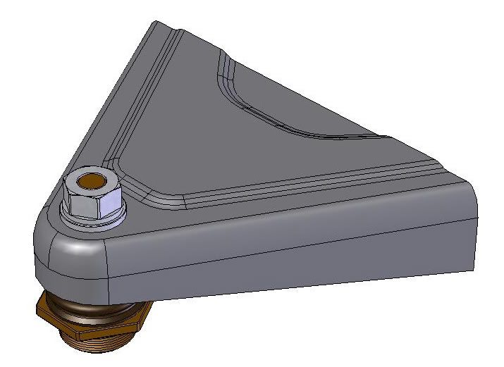 Here is the stock arm from the underside: 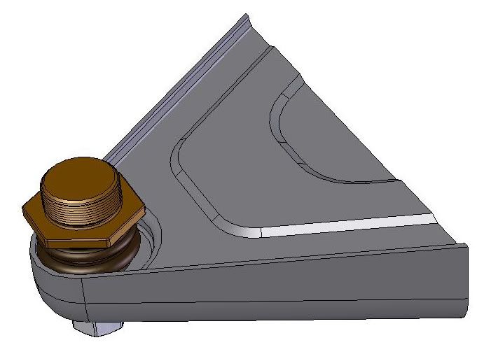 Cut out a stiff paper or cardboard template in a full circle 2.50” diameter. A manila folder is a good thickness for making a template. From the underneath side of the telelever, measure back about .55” +/- .05” from the front edge of the step up where the ball joint is located and mark this point with a pencil. Place the circular template with its outer edge on this mark. Use a pencil or scribe to mark the new arc on the telelever surface. Drill several 1/8” holes up to this marked semi circle through the sheet metal surface with the intention of removing this whole section from the telelever arm. You should drill the holes as close together as possible and use other means to cut between each hole. I used a small jigsaw blade held with visegrips to complete this task. Follow as closely to the welds as possible but no need to get right up to the edge.  There is a large round steel spacer centered on the ball joint hole that is welded in four spots and is attached to the plate you are preparing to remove. Don’t worry if you drill into it in a few spots, just get through the sheet metal and all will be good. When you get the section loose most of the way around, pry up one end and wrestle the whole section out of the telelever arm with visegrip pliers. It will mostly be a twisted mess but the big fat spacer is all you need to save from this piece. Use visegrip pliers and take to a bench grinder and cut through the four welds holding the spacer to the sheet metal and separate the two pieces. Clean up the spacer edges so it lays flat on both sides and set aside. 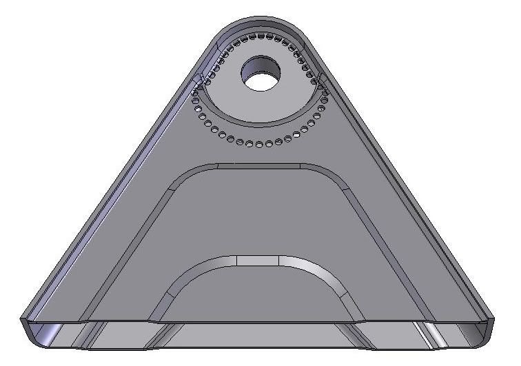 Use a 1/4” rotary grinder to clean up the edges of the cut out section on the telelever arm. No need to get all the old welds out, just clean up the edges as much as you have patience for so that the new piece can be welded in place, partially to the old welds. The drilled section that is away from any welds should be ground fairly smooth for a nice fit with the new parts. Here is what it should look like after prepping.  You will need to order a small section of .094” sheet steel from your local industrial supply. I used a 6”x6” piece of low carbon 1018 steel for good weldability and easy shaping. I also used a 1-1/4” to 1-1/2” diameter by 6” length aluminum rod to be used as a base for flattening a part of the raised area on top of the telelever arm. This is for the ball joint nut clearance and is the next step in the process. You will also need a 3/4" diameter by 3” long bolt with nut to be used as a welding fixture in your final assembly of the new arm. A 1-1/4” length of 3/4” metal water pipe is also useful as a fixture spacer. Use the large diameter aluminum rod, or equivalent, and securely hold it in a bench vise with one end facing up. Prop up the telelever arm so that the aluminum rod protrudes into the cutout section of the telelever arm and the top of the arm lays perfectly flat on top of the aluminum rod. An oxyacetylene gas welder or propane torch can be used to heat the top raised section to a dull red glow and pound flat in a small semicircle for the ball joint nut and plastic cap clearance. Here is how the setup should look from the top: 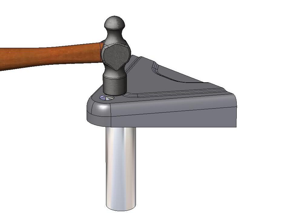 Try not to heat anything but the raised area because you need to maintain the existing flatness of the lower section for alignment purposes. You only need 3/8” to 1/2” clearance from the bottom edge for the ball joint nut and cap so don’t go crazy trying to flatten too large an area. Next, in the corner of your new piece of .094” sheet steel, scribe a circle using the Inside diameter of the large steel spacer you removed from the telelever. Carefully cut and grind a circular disk that will fit inside the top ball joint hole on the telever arm. This will need to be welded in place with a Mig or Tig welder. Before you weld in place this piece, you should again use the large steel spacer to scribe the new ball joint location on the top side of the telelever arm. Carefully measure and center the hole offset 10mm (.394”) directly rearward of the old ball joint hole. Here is a sketch of how to measure the hole offset using the edge of the existing hole as a reference. As long as you maintain the two centerlines perpendicular to one another, you will have perfect front to back alignment of your new hole. This can easily be done by just careful visual observation. 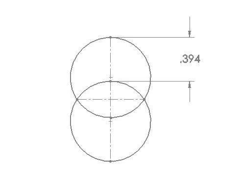 Be sure to use a metal scribe to scratch the new hole position into the surface of the sheet metal. This way you will still have the marks to go by after you have welded and ground flat the metal disk you welded into the old ball joint hole. Now, take the large steel spacer and use it to back up the cut out metal disk on the inside surface of the existing hole and use two c-clamps to hold everything in place for welding. Try to maintain perfect flatness on the inside surface only, which is where the large steel spacer will be positioned on the final assembly. Note that the telelever sheet metal thickness is slightly less (.090”) than the thickness of the disk (.094”), so bias the c-clamps towards the thinner material which will keep the inside surfaces flush with one another. The outside surfaces will be ground flat after welding. Use your Mig welder and tack weld the disk in a three spots and remove the clamps and spacer. Complete the weld of the disk in place. No need to weld the overlap area crossing into the new hole position. This will be cut out when making the new hole. *See next post for the remainder of mod*
__________________
Scott '98 R1100S - Triple Clamps, 10mm Shortened Telelever 2013 KTM 990 SMT, 2008 KTM 990 SDR Last edited by motoyoyo; 09-22-2010 at 08:13 AM.. |
||
|
07-29-2010, 07:53 AM
|
|
|
Registered
Join Date: Aug 2002
Location: Camarillo, CA
Posts: 2,263
|
After welding the disk, use a 4” angled disk grinder and carefully grind the weld flat, along with the .004” extra thickness of the disk material over the .090” thick telelever sheet metal. Be careful not to grind the remaining scribe mark for the new hole position. Place the large steel spacer back in position and carefully align the scribe marks with the hole and fully scribe the new position over the newly welded and ground surface. You will not be able to drill the new hole out to size accurately in one step. Instead, drill progressively to about 5/8” diameter and use a medium diameter round file to carefully complete the new hole bore using the scribe marks as a guide. This is really not as scary as it sounds and you can get quite accurate results with this method.
For gauging the hole size, take the 3/4” x 3” bolt you acquired earlier and use a small lathe to turn down the diameter to approximately .722” so that it just passes through the steel spacer hole. Try to shoot for about .002” clearance but no more than .004”. The closer the fit the more accurate your new hole alignment will be. Also, use the lathe to cut a 1-1/4” long section of a 3/4” metal pipe that will be used later as a spacer for a welding fixture. This piece can be cut by hand but be sure the ends are as flat as you can get them. Now, you will be cutting out the new bottom plate from the .094” sheet metal you acquired earlier. Make a cardboard template to fit the cutout space on the bottom of the telelever arm. Be sure to overlap the cutout by about .050” to.100”. Lay the large steel spacer into position to get the correct height for the bottom plate. Cut away the template until you have the necessary clearances to fit the space. Trace the shape on to the new sheet metal and cut it out using a hacksaw and bench grinder. Use visegrips to hold the piece so that you won’t hurt yourself before you get a chance to try out this awesome mod to your bike. Carefully assemble the large steel ball joint spacer into the telelever arm and use c-clamps to hold the new cut out bottom plate together. Use the turned down 3/4” bolt to align the pieces through the top hole, clamp together with two c-clamps and scribe the hole on the newly formed bottom plate through the top of the telelever. Remove the parts and proceed to cut out the hole in the bottom plate just as described earlier for the new top hole in the telelever arm. Use the bolt and pipe spacer to make a welding fixture and weld the steel ball joint spacer to the new bottom plate. Stitch weld the steel ball joint spacer to the bottom plate in four equally spaced locations. 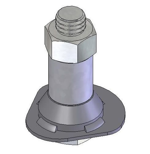 Place the new bottom plate assembly into the telelever arm and again use the bolt and pipe spacer to fixture the parts in place for welding. With everything bolted together tightly you should have perfect alignment of all the parts and are ready to tack weld the bottom plate in place. 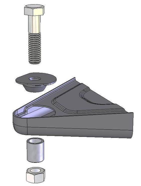 With the remaining .094” sheet steel plate, cut a rectangular strip about 1/2” wide to be used to complete and close the new assembly. You will need to bend this in a semi circle to fit on top of the bottom plate assembly you just welded in place and up against the circular cutout in the telelever arm. This is best accomplished using a hammer and any curved surface on your bench vise. Here is an assembly view of the curved plate ready to be placed into the telelever arm. Here is an assembly view of the curved plate ready to be placed on to the tack welded bottom plate in the telelever arm. 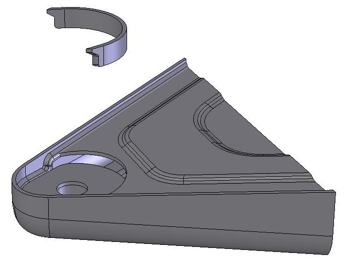 Use C-clamps to hold the curved plate in place and tack weld in a few spots before removing the clamps. Complete the welds on the back side of the curved plate and all around the new bottom plate. You want this to be weather tight so try to fill all the gaps. You will see that the completed telelever arm is at least as strong as it was originally, and this approach has in no way reduced the structural integrity of the arm. You are now ready to prime and paint. I found that a semi gloss Krylon black paint was a good match to the original color. Not too sure about the durability of this paint but you can always have it professionally painted or powdercoated if you feel the need. Get your bike back together and try out it’s new awesomeness and spread the joy to another if you can. This job was a fairly time consuming and required some specialty tools, but it can all be done for less than $40 if you have access to the materials and tools needed. Happy Trails! Finished 10mm shortened version top view: 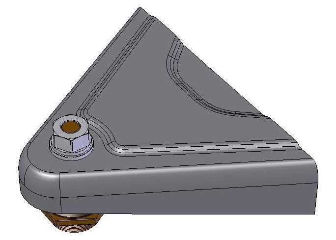 Finished 10mm shortened version bottom view: 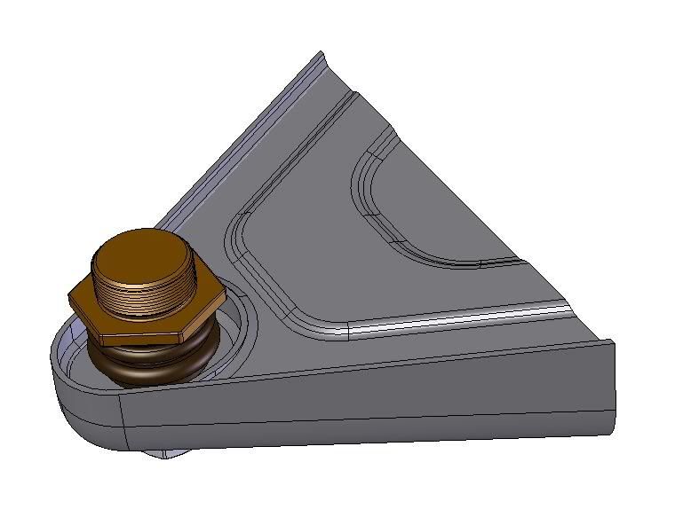 Note: If you have a steering damper mount you should also consider cutting and welding it 3/8” directly rearward on the telelever arm. This will assure the same action and travel of the steering damper as before in the stock position. When setting up your suspension after installing the new shortened telelever arm, you will now be able to take advantage of the 1.2 degree shorter rake angle and 3/4” shorter wheelbase. I have my front laden sag set to around 34-35mm and the rear at 32-34mm. For those of you that have the rear of your motorcycle jacked up to the moon, try lowering the clevis mount adjuster about 2-4 turns to start with, which will bring the seat height down 1/2”-3/4”. The result will still yield a steeper rake angle as well as a lower roll center. All of which contribute to a much better handling and easier to ride motorcycle.
__________________
Scott '98 R1100S - Triple Clamps, 10mm Shortened Telelever 2013 KTM 990 SMT, 2008 KTM 990 SDR Last edited by motoyoyo; 07-30-2010 at 02:06 PM.. |
||
|
07-29-2010, 07:55 AM
|
|


