|
|
|
|
|
| Author |
|
|
Registered

|
Is your post saying you are not measuring a 6 MHz clock on the good DME on pin 19 but instead something different?
Are you using a 10:1 probe with ground and is the oscilloscope set up properly?
__________________
1974 Targa 3.6, 2001 C4 (sold), 2019 GT3RS, 2000 ML430 I repair/rebuild Bosch CDI Boxes and Porsche Motronic DMEs Porsche "Hammer" or Porsche PST2, PIWIS III - I can help!! How about a NoBadDays DualChip for 964 or '95 993 |
||
 07-05-2025, 02:10 PM
|
|
|
Registered
Join Date: Aug 2018
Posts: 34
|
Quote:
Is that perhaps a typo on your end, Ingo? 2. Instead of 6 I'm measuring 3.3-3.8 MHz Re 2 I had the following thought. Seeing that a known 1kHz signal is represented as a 631Hz signal on the scope, I.e. 1.583x too small, the same will probably the case for any other signal displayed. I measured 3.3 to 3.8 MHz on pin 18. Let's multiply that by the same factor... Low and behold 3.8 x 1.583=6.02 MHz! I use a 1:1 probe with ground at pin 20. I'm certain I have set the scope up correctly, all according to the manual I have for it. I suspect that x-control is off as the line starts before the first x-division an stops only after having overshot the last division. Multiplying the frequencies measured with the Hameg scope by 1.58 yields for the OK DME Pin 5 OK: 9.2V 79Hz Pin 9 OK: 0.435V DC Pin 18 OK: 2,4Vpp (0.3-2.7V) 6 MHz Pin 19 OK: 1.2V- 1.3 V 26Hz Pin 30 ALE OK: 6.7V at 1 MHz (corresponding to 1/6th of oscillator freq and acc. to spec) Pin 40 OK: 4.95 V DC Adv11 OK 7,3V 79Hz Last edited by hardtailer; 07-06-2025 at 03:53 AM.. |
||
|
07-05-2025, 11:54 PM
|
|
|
Registered
|
Pin 18 is fine for the clock. With a more sensitive probe youll see the 6MHz on both pins at different intensities. Id get a 10:1 probe as the 1:1 version will load up signals and may interfere with measurements.
Your scope seems to have its time base out of calibration. Good find. Now that you know how to confirm clock & ALE check for the same signals on the other DME. Without clock it will be brain-dead and not execute code.
__________________
1974 Targa 3.6, 2001 C4 (sold), 2019 GT3RS, 2000 ML430 I repair/rebuild Bosch CDI Boxes and Porsche Motronic DMEs Porsche "Hammer" or Porsche PST2, PIWIS III - I can help!! How about a NoBadDays DualChip for 964 or '95 993 |
||
|
07-06-2025, 05:44 AM
|
|
|
Registered
Join Date: Aug 2018
Posts: 34
|
Quote:
Is there a way to check the 2 capacitors and the 6MHz crystal in circuit using a scope and or DMM (with diode check)? |
||
|
07-07-2025, 01:51 PM
|
|
|
Registered
|
According to the data sheet pin 18 and 19 are the input and outputs of an inverting amplifier of the 8051. With the quartz and the capacitors in place this should produce the clock signal. If you have the right equipment you can isolate pin 18 by removing R720 and feed a 6 MHz clock signal into pin 18. Short pin 19 to pin 20. If that still doesn't produce signs of life the 8051 is bad.
You might be able to check pin 18 and pin 19 with a high-quality DVM in diode mode and compare it against the good DME. However, I'd caution that these older 8051 are not as rugged as current devices and the last thing you want is to kill the second unit in the process. So proceed with caution and fully understand the data sheet, the absolute maximum ratings and your test equipment. You can desolder the capacitors and replace them (easy) or test them with an LCR meter but it is virtually unheard of that these go bad. Same for the quartz, replacing it is straightforward but I don't know how to test it short of having a vector network analyzer. And for the price of one of those you can probably buy 10 new DME units.... Also the quartz going bad is not a common failure mode and highly unlikely, especially due to a short on the analog board. It is more conceivable that the +5V rail took a hit when you shorted things and that killed components on the logic board powered by +5V (MCU, ADC, EPROM, glue logic).
__________________
1974 Targa 3.6, 2001 C4 (sold), 2019 GT3RS, 2000 ML430 I repair/rebuild Bosch CDI Boxes and Porsche Motronic DMEs Porsche "Hammer" or Porsche PST2, PIWIS III - I can help!! How about a NoBadDays DualChip for 964 or '95 993 |
||
|
07-07-2025, 02:43 PM
|
|
|
Registered
Join Date: Feb 2014
Location: Lomita, CA
Posts: 2,686
|
Just buy a 8051 chip & a 40 pin socket from eBay for troubleshooting, less than a $25 effort.
All the code runs off of the 64K(8K bytes) EPROM, anyway.
__________________
Dave Last edited by mysocal911; 07-07-2025 at 06:50 PM.. |
||
|
07-07-2025, 06:31 PM
|
|

|
|
Registered
Join Date: Aug 2018
Posts: 34
|
Thanks for your responses.
Since I have no means of feeding a 6MHz signal into the uC I have ordered the part(s). |
||
|
07-08-2025, 05:57 AM
|
|
|
Registered
Join Date: Aug 2018
Posts: 34
|
Parts arrived yesterday and I fitted the 40 Pin socket and 8051 uC replacement.
Unfortunately Pin 9 is still receiving the reset signal and Pin 5 is at a steady 5V or so. However, I do have an oscillation on pin 18 and 19, so that's a win. Pin 30, ALE looks as depicted. What's with that? Looks like 2 superimposed signals... Is that a pointer to a defective part?     I switched to 1:10 attenuated probe after the pictures were taken. Unfortunately my old scope keeps blowing its fuse, so can't use that at the moment... I desoldered the 2 capacitors connected to the oscillator, as well as c890 and measured their capacitance and they are all within 10% of their nominal spec too. I checked the diodes in the circuit around the comparator, D890 and D891 and they are fine. Since the uC kept getting the reset signal I replaced S890/LM139 but the outputs of all 4 comparators inside it remained unchanged. Both the 1012 transistor and the 5V regulator remain almost at ambient/room temp when the DME is powered, another positive change. All other IC's receive steady 5V supply and are grounded. Nonetheless the reset signal keeps being sent. Where do I look into next? Last edited by hardtailer; 07-12-2025 at 01:51 PM.. |
||
|
07-12-2025, 01:34 PM
|
|
|
Registered
|
For pin 30 you see aliasing of the reset signal with the ALE signal because your time base is incorrect for a 1 MHz signal. It needs to be 1 us or thereabouts.
Once you have confirmed the ALE signal check or replace the transparent latch and the EPROM. Given you blew the 8051 these might also be compromised. And the same is true for the ADC. Even though it’s not needed to feed the watchdog it could still compromise the address or data bus. I’d get it out of the circuit for now.
__________________
1974 Targa 3.6, 2001 C4 (sold), 2019 GT3RS, 2000 ML430 I repair/rebuild Bosch CDI Boxes and Porsche Motronic DMEs Porsche "Hammer" or Porsche PST2, PIWIS III - I can help!! How about a NoBadDays DualChip for 964 or '95 993 |
||
|
07-12-2025, 08:23 PM
|
|
|
Registered
Join Date: Aug 2018
Posts: 34
|
Thanks for your reply.
I measured Pin 30 on uC (the 8051 replacement is an Atmel AT89C55WD) at 1us but signal still showed aliasing. Did that on the OK DME too, FWIW. I'm surprised to see in the reset signal what looks like the inverted saw tooth of Pin 6/S890 lm139. Perhaps it is not aliasing at all? I removed the ADC which did not change the reset signal With it removed I replaced the EPROM, S702 transparent state latch, S704 hex buffer/converter and S705 - 74LS02 gate and checked the Pin 9 reset signal on the uC 8051 in between each and every replacement. Unfortunately it never changed from the signal shown in the last picture of it, I.e. square wave going high at ~30 Hz. Putting the ADC back didn't change it either. |
||
|
07-13-2025, 03:26 AM
|
|
|
Registered
Join Date: Feb 2014
Location: Lomita, CA
Posts: 2,686
|
Ground pin 9 of the 8051 and check its the data & address buses for basic operations.
Without data and instructions from the EPROM, the 8051 can never exit the reset mode.
__________________
Dave Last edited by mysocal911; 07-13-2025 at 09:45 AM.. |
||
|
07-13-2025, 04:51 AM
|
|
|
Registered
Join Date: Aug 2018
Posts: 34
|
Thanks for your reply.
I connected pin 9 straight to ground. Measuring pin 30, ALE was a saw tooth like shown above for Pin 6 of S890 but later on it was a steady ~Vcc. Pin 33 and 34 to the (not connected) ICV showed no irregular signal as it did before. Input signals to uC 8051 AD0 to 7 were all steady voltages for each, no repetitive signal. What should I be looking for exactly? |
||
|
07-13-2025, 10:32 AM
|
|

|
|
Registered
|
You have a good working DME. Use your oscilloscope and measure the ALE signal. You need to be able to see the 1 MHz clearly. And then do the same on the other DME. There shouldnt be any triangle signal whatsoever. The ALE signal is required for the 8051 to access its external address space.
The watchdog circuit monitors the ICV output of the 8051. If the program is properly running there is a square wave and that satisfies (feeds) the watchdog. If for some reason this square wave doesnt get produced the watchdog triggers and brings the reset pin to logic high and then after a certain period brings the reset pin to logic low. This resets the 8051 and it starts to execute code from the reset vector. The reset vector is located at 0x0000. In your case the watchdog keeps resetting the 8051 because (1) there is no activity on the ICV output or (2) because the watchdog circuit itself is damaged and doesnt recognize the ICV signal. If you trigger the oscilloscope on the high-to-low transition of the reset line while measuring the ICV output you should be able to tell what case youre dealing with.
__________________
1974 Targa 3.6, 2001 C4 (sold), 2019 GT3RS, 2000 ML430 I repair/rebuild Bosch CDI Boxes and Porsche Motronic DMEs Porsche "Hammer" or Porsche PST2, PIWIS III - I can help!! How about a NoBadDays DualChip for 964 or '95 993 |
||
|
07-13-2025, 12:16 PM
|
|
|
Registered
Join Date: Feb 2014
Location: Lomita, CA
Posts: 2,686
|
Quote:
it's on same logic bus.
__________________
Dave Last edited by mysocal911; 07-13-2025 at 01:15 PM.. |
||
|
07-13-2025, 12:47 PM
|
|
|
Registered
|
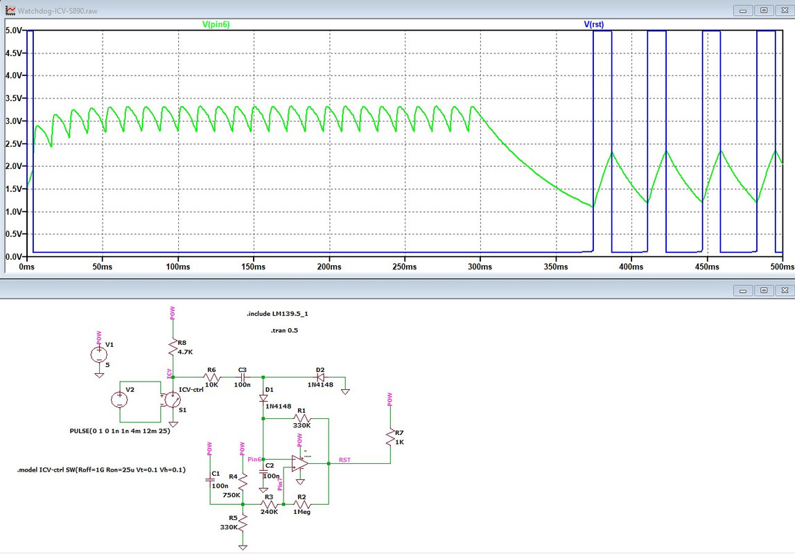
Your watchdog circuit is OK. I think you can leave it alone. Here is another screenshot I took again from my SPICE simulation of the watchdog circuit. I simulated normal presence of ICV pulses coming from µC pin 5, followed by a sudden stop of these pulses at 300ms. Signal in green is what appears on pin 6 of LM139. Signal in blue is RST line. Small green saw tooth signal on left is when normal ICV signal (from µC pin 5) is present. RST line remains low, situation normal. Then when ICV pulses stop being received by the watchdog, large saw tooth signal similar to what you see on your not OK unit begins to appear. That is the result of the watchdog circuit entering a different oscillation mode due to the absence of ICV pulses. That allows it to send RST pulses every 30 ms or so.
__________________
Gilles RoW 88 Carrera coupé |
||
|
07-14-2025, 12:02 AM
|
|
|
Registered
|
One more thought. Probably silly, but make sure pin 31 (!EA) on S700 is grounded. It needs to be grounded so the MCU can read code from the external EPROM and not from its internal memory. There should be a jumper for this.
However this check is probably useless as your ECU has a 28-pin EPROM.
__________________
Gilles RoW 88 Carrera coupé |
||
|
07-14-2025, 03:09 AM
|
|
|
Registered
|
This thread is turning out to be a very informative' and helpful' resource to anyone who [like me] want's to learn more about how these units work, what controls what, and the fault finding aspect, big thanks to all who have contributed so far, and hopefully it will help greatly in the OP fixing his original issue.
 Ant.
__________________
"But instinct is something which transcends Knowledge We have undoubtedly certain finer fibres that enable us to perceive truths when logical deduction or any other wilful effort of the brain is futile" Nikola Tesla Last edited by ant7; 07-14-2025 at 04:56 AM.. |
||
|
07-14-2025, 04:34 AM
|
|
|
Registered
Join Date: Aug 2018
Posts: 34
|
Thanks for all contributions, guys.
I'll work on the DME again this weekend and report my findings. |
||
|
07-16-2025, 06:55 AM
|
|
|
Registered
Join Date: Aug 2018
Posts: 34
|
Using my scope I get on the nOK DME
S700, 8051 Pin 5 NOK 4.96 V DC Pin 9 NOK 24 Hz square Pin 18 NOK 5.5 MHz sinus wave Pin 19 NOK 5.6 MHz sinus wave Pin 30 NOK 1MHz square Pin 31 ground (thru jumpers B9 and B700) Pin 33, 34 ~1.2 MHz square wave    So square wave at 1 MHz confirms ALE on pin 30 being as it should be. Signals on pin 33 and 34 looked identical to eachother after a minute or so (see pic below). I reckon that's down to the scope as it keeps blowing its slow 0.2A fuse after 15 minutes or so. Update: with the correct slow fuse it doesn't blow anymore... For comparison, signal on pin 34 of working DME looks like  On S890, lm139 Pin 6 NOK 22Hz Pin 7 NOK 22Hz I grounded pin 9 Reset of S700 using a microswitch and saw pin 30 ALE momentarily change from square signal to a solid ~5V DC before reverting to the square wave, whilst keeping it grounded. I could not get this solid 5V DC signal after this. Shorting pin 9 to ground did no longer change the square signal. What did I damage? Signal from pin33 no longer looks like the picture either... Referring to post #73: Pin 5 is a steady 4.96V so no ICV signal and therefore the uC keeps resetting. As shown by wazzz in #74 watchdog seems fine. Update: I have changed the EPROM to the one out of the working DME. Pin 5 remains at 4.96V DC and thus the uC keeps resetting. I also replaced S700 and the lm139 after pulling pin 9 to ground but no change in pin 33 signal, it doesn't look like it in the pic for pin 33 above but resembles the pic for the signal on pin 34. Last edited by hardtailer; 07-23-2025 at 12:35 PM.. |
||
|
07-20-2025, 01:54 PM
|
|
|
Registered
|
Uh oh, sinus waves....🤧🌊
|
||
|
07-20-2025, 02:46 PM
|
|


 1974 Porsche 911 Targa 3.6


 88 Carrera coupé
 1985 Porsche 911 3.2 Carrera Sport
 Wicked Witch of the East
