|
|
|
|
|
| Author |
|
|
Registered
Join Date: Aug 2018
Posts: 34
|
I updated my last post but decided to put the picture in this separate/new post.
 This is what the signal op pin 33 currently looks like... Last edited by hardtailer; 07-23-2025 at 01:22 PM.. |
||
 07-23-2025, 01:19 PM
|
|
|
Registered

|
I hate to sound like a broken record but you are not supplying any new information. The watchdog keeps triggering and pulls the RST line high for 12 msec and then pulls it low for 24 msec. Refer to the second portion of the SPICE simulation Gilles posted. This results in the a 36 msec or 28 Hz pattern most pins of the 8051.
When the RST line is pulled high the 8051 halts all activities on the bus and that lasts for 12 msec. Once the RST line goes low for 24 msec there appears to be activity that your current scope settings are not resolving. If the code doesn't produce a proper ICV signal on pin 5 of the 8051 this keeps repeating. Put the oscilloscope on pin 5 of the 8051. If you see the same 30 Hz pattern your DME is brain-dead. If you see an 80Hz ICV signal you can go to the next step of troubleshooting.
__________________
1974 Targa 3.6, 2001 C4 (sold), 2019 GT3RS, 2000 ML430 I repair/rebuild Bosch CDI Boxes and Porsche Motronic DMEs Porsche "Hammer" or Porsche PST2, PIWIS III - I can help!! How about a NoBadDays DualChip for 964 or '95 993 |
||
|
07-23-2025, 06:26 PM
|
|
|
Registered
Join Date: Aug 2018
Posts: 34
|
Thanks for hanging in there with me.
I checked the 3 EPROMs I have, to identify those which work in the OK DME and found that the one that was in the NOK DME during the short circuit is damaged. Putting the known good EPROM in the NOK DME I still get the reset signal on pin 9 of the uC... Jumpers to make the DME work with 256kB EPROM are identical in both DME's: B700, B701, B705, B706 To summarize: -All IC's replaced apart from S703 ADC -known working EPROM -5V DC supply to the digital board after replacement of 5V regulator and track on analog PCB. .All diodes tested ok -All capacitors tested ok -ALE signal of 8051 replacement correct at 1MHz But 8051 replacement keeps resetting. Where do I look next? |
||
|
07-24-2025, 12:49 PM
|
|
|
Registered
|
The digital part of the DME is extremely simple and you already have clock. That leaves the address and data bus realized by a transparent latch and a couple of pull-up resistors on the higher address lines. The only other item is a NOR gate to generate the OE! for the EPROM.
Remove the ADC, power up the DME and then disable the watchdog by grounding the RST pin of the 8051. Look at the pin 5 for the 80Hz ICV signal. If present the watchdog circuit is damaged. If not present its an issues on the PCB (shorts, opens, etc.) or one of the components (8051, EPROM, 74LS373, 74LS02).
__________________
1974 Targa 3.6, 2001 C4 (sold), 2019 GT3RS, 2000 ML430 I repair/rebuild Bosch CDI Boxes and Porsche Motronic DMEs Porsche "Hammer" or Porsche PST2, PIWIS III - I can help!! How about a NoBadDays DualChip for 964 or '95 993 |
||
|
07-24-2025, 02:23 PM
|
|
|
Registered
Join Date: Aug 2018
Posts: 34
|
Thanks for your reply, I'll give that a go.
Can I pull pin 9 to ground directly, without a resistor inline (as R892/1kOhms is there)? |
||
|
07-24-2025, 09:53 PM
|
|
|
Registered
Join Date: Aug 2018
Posts: 34
|
Thanks for your reply, I'll give that a go.
Can I pull pin 9 to ground directly, without a resistor inline (as R892/1kOhms is there)? |
||
|
07-24-2025, 11:07 PM
|
|

|
|
Registered
|
Quote:
You should also check and maybe replace the 74LS373 as well as the ADC. And maybe set all packages on sockets so they can easily be replaced without being soldered. On a side note, how did you manage to remove the 40-pin MCU? Did you unsolder it as a whole with a heat gun or did you use cutting pliers to cut each pin first then unsolder and clean each pad separately?
__________________
Gilles RoW 88 Carrera coupé |
||
|
07-25-2025, 12:56 AM
|
|
|
Registered
Join Date: Feb 2014
Location: Lomita, CA
Posts: 2,686
|
Quote:
__________________
Dave |
||
|
07-25-2025, 07:15 AM
|
|
|
Registered
Join Date: Aug 2018
Posts: 34
|
Thanks for chiming in, Gilles.
Knowing me, I used sockets on all IC's I have replaced in the meantime and bought 2 of each IC �� The ADC is not readily available anymore in DIP-package, so have not bought that (yet). Apart from this one and S100 I've replaced all IC's on the digital board. I desoldered the uC using flux, solder sucker and de-solder wick 'soaked' in flux. Worked well, all pads stayed on the pcb. |
||
|
07-25-2025, 07:54 AM
|
|
|
Registered
Join Date: Feb 2014
Location: Lomita, CA
Posts: 2,686
|
Quote:
A simple approach is to just cut the two rivets at the PCB and remove complete heat sink assembly, after desoldering the devices attached to the assembly.
__________________
Dave Last edited by mysocal911; 07-25-2025 at 08:25 AM.. |
||
|
07-25-2025, 08:20 AM
|
|
|
Registered
|
Quote:
Only $2.90 plus $4.00 for shipping.
__________________
Gilles RoW 88 Carrera coupé |
||
|
07-25-2025, 09:59 AM
|
|
|
Registered
Join Date: Aug 2018
Posts: 34
|
Thanks for the link. After contacting futurlec to check if they had it in stock, I ordered the last ADC they had.
Having removed the ADC I checked the signal on pin 5 of the 8051 replacement but rit didn't show the ~80Hz signal., unfortunately. I also bought a logic analyzer https://www.embeddedartists.com/products/labtool/ but installing the drivers is a royal pain and I've not managed to get it to work. Contacted their product support and am awaiting their reply. I hope to identify with it why the uC keeps receiving the reset signal. Till I get it working progress has halted, unfortunately. Last edited by hardtailer; 08-03-2025 at 01:33 PM.. |
||
|
08-03-2025, 01:22 PM
|
|
|
Registered
Join Date: Aug 2018
Posts: 34
|
Quote:
Parts from Futurelec are still underway but I got the logic analyzer working. Picture below shows the (un)grounding of the reset pin 9 on 8051 with ADC removed @20kHz sampling rate.  I then observed the following, sporadic behaviour (not pulling pin 9 to ground), again at 20kHz  Looks to me that the few times when pin 5 goes from high to low, the appearing signal form at pin 6 of LM373 starts to look like it does in wazzz's simulation between +20 and +31.1 ms. Analyzing LM373 more closely:  Can the experts deduct anything from these graphs regarding cause of uC resetting continuously? For completeness sake the 4th OPAMP connected to uC pin 10 RXD:  Other signals on the uC 8051: @20kHz, pins 2 to 9 RST, 18 XTAL2, 19 XTAL1 and 30  pins 21-24 and 32-40  pins 21-24 and 32-40, some moments later  the above are repetitive (no surprise there). @30MHz (f_ALE=1MHz, f_XTAL2=6MHz)  @30 MHz  Next EEPROM 27C256 pins 2 to 13 (13= analogue channel just to use all available channels), @20MHz 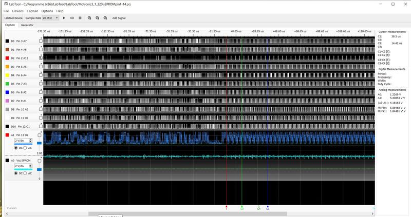 ADC removed in all graphs. I found no short and open circuits (used a magnifying glass) and all IC's have been replaced in the process. That is not to say that they have become damaged again in the process but still. I don't know how to check the transparent latch or "the only other item is a NOR gate to generate the OE! for the EPROM". |
||
|
08-10-2025, 05:55 AM
|
|
|
Registered
|
Sample A0-A13 with 1Mhz using the external clock input of the logic analyzer connected to ALE and trigger to RST. Sample on the falling edge of ALE. You should be able to decode the long jump from 0x0000 to the reset vector.
__________________
1974 Targa 3.6, 2001 C4 (sold), 2019 GT3RS, 2000 ML430 I repair/rebuild Bosch CDI Boxes and Porsche Motronic DMEs Porsche "Hammer" or Porsche PST2, PIWIS III - I can help!! How about a NoBadDays DualChip for 964 or '95 993 |
||
|
08-10-2025, 06:03 AM
|
|
|
Registered
Join Date: Feb 2014
Location: Lomita, CA
Posts: 2,686
|
At this point in time, you most likely have a logic PCB problem, e.g. an open circuit trace, a poor top/bottom jumper, or a damaged solder connection.
Also, the PCBs are the early non-fiberglass types which are less reliable.
__________________
Dave |
||
|
08-10-2025, 09:47 AM
|
|
|
Registered
|
This one is fiber glass, I think. hardtailer posted pics of it a few weeks ago. Remember, it comes from a BMW M3 E30.
__________________
Gilles RoW 88 Carrera coupé |
||
|
08-10-2025, 10:38 AM
|
|
|
Registered
|
Here is an example of a healthy startup. Shortly after the reset goes low the 8051 starts reading the first instruction at address 0x0000. The first three bytes in the EPROM are 02 02 0f and this decodes to LJMP 0x020f where the reset routine below starts. The code on your DME is in all likelihood identical:
 In the logic analyzer trace you can see the processor reading the first three bytes and then executing the LJMP to 0x020f where it continues to read external code memory.  Zooming out in the logic analyzer capture you can see where the ICV signal begins cycling by going low 17.84ms after reset and then high 23.38ms after reset. Signal period is 11.68ms or 85.6Hz.  So in summary 17ms after powerup the DME is ready and waiting for flywheel inputs. Sorry for the picture quality. I don't know if there is a way where the BBS software doesn't down sample them.
__________________
1974 Targa 3.6, 2001 C4 (sold), 2019 GT3RS, 2000 ML430 I repair/rebuild Bosch CDI Boxes and Porsche Motronic DMEs Porsche "Hammer" or Porsche PST2, PIWIS III - I can help!! How about a NoBadDays DualChip for 964 or '95 993 Last edited by ischmitz; 08-10-2025 at 12:27 PM.. |
||
|
08-10-2025, 12:25 PM
|
|
|
Registered
Join Date: Feb 2014
Location: Lomita, CA
Posts: 2,686
|
Quote:
The key is the side view of the PCB. All have green tops/bottoms, but the early ones are beige in the middle.
__________________
Dave |
||
|
08-10-2025, 12:27 PM
|
|

|
|
Registered
Join Date: Aug 2018
Posts: 34
|
Thanks for re-visiting and your inputs, gentlemen!
Unfortunately, my logic analyzer does not have a provision/input to use an external clock. It has 11 channels + 2 channel oscilloscope, so hooking up A0-A12 (didnt see A13 on the schematics, was that a typo?) already forces me to use the oscilloscope to scope digital signals and leaves no means of connecting ALE and RST to the analyzer for sample and trigger. What pin is the channel designated 'parallel' im your graph, Ingo? Tbh I don't understand how I get the hex code. I connected A0-A7, RST, ALE, RXD (UART decode to HEX, @9600 baud), TXD (same decode) and PSNE but the decode didnt yield any sensible results. PCB is fibreglass. Last edited by hardtailer; 08-10-2025 at 03:11 PM.. |
||
|
08-10-2025, 02:42 PM
|
|
|
Registered
|
The channel “Parallel” is a protocol decoder that uses the address lines to calculates a hexadecimal number. It makes the data more readable.
You don’t need clock or other inputs. Just sample the address signals A0 - A9 on the EPROM. If your init LJMP uses the same argument (check your EPROM content first three bytes) you only need A0 - A9 to confirm the LJMP takes place. That leaves one more digital line you may use for trigger on RST or something else. I used 10Mhz sampling and no clock. If you don’t have a way to trigger off the RST line just sample for a coupe of seconds start the data collection, and power on. Then find when RST goes low in the data. Check the EPROM content for the first three bytes and confirm the 8051 reads the first three bytes and jumps to the correct address.
__________________
1974 Targa 3.6, 2001 C4 (sold), 2019 GT3RS, 2000 ML430 I repair/rebuild Bosch CDI Boxes and Porsche Motronic DMEs Porsche "Hammer" or Porsche PST2, PIWIS III - I can help!! How about a NoBadDays DualChip for 964 or '95 993 |
||
|
08-10-2025, 03:00 PM
|
|


 1974 Porsche 911 Targa 3.6
 88 Carrera coupé


