|
|
|
|
|
| Author |
|
|
Registered
|
Quote:
 Great weekend for ya in the Norfland Bro! Great weekend for ya in the Norfland Bro!
__________________
Karl ~~~ Current: '80 Silver Targa w /'85 3.2. 964 cams, SSI, Dansk 2 in 1 out muf, custom fuel feed with spin on filter Prior: '77 Copper 924. '73 Black 914. '74 White Carrera. '79 Silver, Black, Anthracite 930s. |
||
 11-11-2016, 04:08 AM
|
|
|
Registered

|
Simply clean Karl.
I'm flat bedding the kuehl machine to you so you can wire in my new AEM engine management.
__________________
Kuehl 1987 911 cab, modified https://griffiths.com/ |
||
|
11-11-2016, 10:35 AM
|
|
|
Registered
|
^^^ TY to ya up in NJ! Just looked over AEM's stuff... Very inspiring. Send Kuehlmachine on down---(will finally put eyes on your mysterious zupercharger program.)
I looked at this documentary a while ago... so don't recall if your location is "on the map." Am thinking you're in close proximity if nothing else. If you are not in the mood for a vid-doc on how fooked up things are... don't watch. (Is fracking doc. For the industry to call it "clean energy" is possibly the biggest marketing BS campaign of all time. Not a feel good vid.) https://www.youtube.com/watch?v=Xvz_m5uPV4s&feature=youtu.be
__________________
Karl ~~~ Current: '80 Silver Targa w /'85 3.2. 964 cams, SSI, Dansk 2 in 1 out muf, custom fuel feed with spin on filter Prior: '77 Copper 924. '73 Black 914. '74 White Carrera. '79 Silver, Black, Anthracite 930s. Last edited by Discseven; 11-12-2016 at 05:48 AM.. Reason: (Is fracking doc... |
||
|
11-11-2016, 03:49 PM
|
|
|
Registered
|
Compressor relay. 12v from car and 5v from Arduino will go to this. Relay is mounted inside box on short nylon posts. Will feed wires into opposite sides of box.
     Console disconnect. 15 pin / 2 row female pin port. (Am not an electrical guy so am learning on the fly here. Looking at this port it seems power and ground could have been done smarter---rather than serving +|- from AC control box panel through multiple wires to this point, +|- could instead have been just 2 wires run from the control box panel to this point. At this port, +|- could then have been bridged across pins as needed. Am questioning now if one way is actually functionally better than another? If anyone can shed some light on this please do.)    System harness cable. Will hard-wire this stuff into male side of console disconnect. Individual cables run to: Ambient sensor* | Cabin sensor* | Evap core temp sensor | Relay | Dimmer switch. Is 26 gauge stranded wire stuffed into heat shrink sheath. After shrinking I realized a better look could be achieved by combing the wires as theyre fed into sheath. This would also have been nice to do to the cable from control box to console disconnect. Since, in this case, these cables are all hidden, doesnt matter much. For exposed cable, comb-feeding would be a nice touch. (Longer cable---7---needed to be done in overlapping sheath sections. I tried to rig 1 wire to pull 3 through the sheath but config was too thick for sheath. Feeding as much wire as would go into a sheath then cutting the sheath and starting a new section works fine. Where the sheath overlaps is not noticed unless looking for it.) Ran out of black heat shrink and so the exposed wires that remain to be covered. * Temp & humidity. 
__________________
Karl ~~~ Current: '80 Silver Targa w /'85 3.2. 964 cams, SSI, Dansk 2 in 1 out muf, custom fuel feed with spin on filter Prior: '77 Copper 924. '73 Black 914. '74 White Carrera. '79 Silver, Black, Anthracite 930s. |
||
|
11-12-2016, 07:44 AM
|
|
|
Registered
|
Dimmer switch location. Positioning dimmer switch under the dash is doable but is a lean-forward-to-adjust position (for me.) I like the idea of hiding this switch but not at the expense of sensible ergonomics. So a change in plan...
Below is not my '80 dash but a match to it except for stereo. I have exact same 2 available stock switch locations this dash shows. The metal sub-dash is already hole-punched (at least near steering wheel location) so only the cover would have to be punched out. Use a Porsche knob and a switch at either location would finish off looking stock. (What insert to use in a knob can be sorted later.) Putting the dimmer near the steering wheel... makes sense to me... ...Not happening. Potentiometer's thread section and shaft are too short for the thickness of the dash panel. Since potentiometer on hand is the one John built the system model with and it's already proven to work... shopping a replacement pot with specs that will fit dash but might or might not work is not an appealing idea.  Now taking mounting surface thickness into consideration... is possible to mimic the intermittent wiper switch location. Use an intermittent knob and this has potential. Doesn't "feel" right to me so more mulling it over. Conclusion is to locate dimmer below and to the left of fuel gauge. Metal is thin enough to accept pot here... good ergos... switch is sort of hidden... and should there be reason to remove it later, hole can be refinished so no visible trace remains. 
__________________
Karl ~~~ Current: '80 Silver Targa w /'85 3.2. 964 cams, SSI, Dansk 2 in 1 out muf, custom fuel feed with spin on filter Prior: '77 Copper 924. '73 Black 914. '74 White Carrera. '79 Silver, Black, Anthracite 930s. |
||
|
11-12-2016, 08:23 AM
|
|
|
Registered
Join Date: Apr 2008
Location: Miami
Posts: 963
|
Hello Karl. No need to stick to that pot. Anything else that's a linear pot will work. Something at or above 10K. The pot will act as a voltage divider no matter the ohms and act the same as far as the arduino is concerned.
__________________
1979 SC, Slant nose wide-body cab conversion. AEM Infinity EFI, COP, supercharged! |
||
|
11-12-2016, 02:54 PM
|
|

|
|
Registered
|
^^^ Hey John... thanks for note. Will see tomorrow if Master Electronics has pot that will fit stock location in dash.
If you would, take a look at 2nd paragraph ("Console Disconnect") post #124. Am questioning how best to run power & ground---think the way I did it was less efficient than it could have been.
__________________
Karl ~~~ Current: '80 Silver Targa w /'85 3.2. 964 cams, SSI, Dansk 2 in 1 out muf, custom fuel feed with spin on filter Prior: '77 Copper 924. '73 Black 914. '74 White Carrera. '79 Silver, Black, Anthracite 930s. |
||
|
11-13-2016, 07:49 AM
|
|
|
Registered
|
Usually Digi Key is a reasonable source to search and drill down based upon component characteristics you want; and they have pdf specs you can pull up as well.
__________________
Kuehl 1987 911 cab, modified https://griffiths.com/ |
||
|
11-13-2016, 08:18 AM
|
|
|
Registered
|
^^^ Yeah... Digi Key has good variety of stuff, pics and PDFs---and nice filters. Believe existing pots came from DK. If I can get final missing bits from local place this morning... system can bench test this afternoon.
__________________
Karl ~~~ Current: '80 Silver Targa w /'85 3.2. 964 cams, SSI, Dansk 2 in 1 out muf, custom fuel feed with spin on filter Prior: '77 Copper 924. '73 Black 914. '74 White Carrera. '79 Silver, Black, Anthracite 930s. |
||
|
11-14-2016, 06:02 AM
|
|
|
Registered
Join Date: Apr 2008
Location: Miami
Posts: 963
|
Quote:
__________________
1979 SC, Slant nose wide-body cab conversion. AEM Infinity EFI, COP, supercharged! |
||
|
11-14-2016, 05:14 PM
|
|
|
Registered
|
^^^ Thanks for input John. Yeah... gona leave it as is.
Master Electronics did not have 10k pot with longer thread & shaft. Am moving on with pot in hand. Will install below and to left of fuel gauge---ergo is good there and is easy wire feed.  Harness terminal. Too much heat when soldering melted casing. Tossed this and started over (using alternate soldering technique…)   Found it works better (for this newb solderer) to melt solder to wire… then position wire in pin cup… then melt solder.  Wires (above) are from evaporator temp sensor. Power/red has been spliced to ground at junction (on sensor’s side) so red wire is dead at this point. White is signal wire---runs to Distribution Panel where it splits---one side goes to signal pin at Ard, other side goes through 4.7k resistor to power. Black is ground. Dead-end red wire from evap sensor is inside port cap. Could have made this cable with 2 wires and saved some grommet space… used 3-wire cable provided with evap’s sensor instead.  Harness is almost done. Still need to make and connect a relay cable (“IN2” and Arduino power) to this. Looking at this... realize it's possible evap junction will not fit through bulkhead. As I recall the feed hole for the capillary (in '80 911) is not much bigger than capillary. Perhaps I'm wrong. CG...????  Relay box. Black cable serves Arduino power (VCC) and signal (IN2)---signals compressor ON/OFF. Red cable serves relay non-Arduino power (JD-VCC) and related ground. Exactly what the second power (JD-VCC) line does... I'm not clear on. John, perhaps you would elaborate on this. Plan is to Velcro “nut-side” of box to bulkhead below dash. 12v side has yet to be done. (Will bench-test relay signalling compressor ON/OFF using multimeter.) EDIT: Some rewiring will be done here later. JD-VCC and ground requires 12v wire as opposed to 26 gauge for 5v as is wired here. John's program also specifies "IN1"... not "IN2" for signaling. Eventually these errors will be found and corrected.  
__________________
Karl ~~~ Current: '80 Silver Targa w /'85 3.2. 964 cams, SSI, Dansk 2 in 1 out muf, custom fuel feed with spin on filter Prior: '77 Copper 924. '73 Black 914. '74 White Carrera. '79 Silver, Black, Anthracite 930s. Last edited by Discseven; 11-21-2016 at 07:23 AM.. Reason: "EDIT: Some rewiring will be done later..." |
||
|
11-15-2016, 09:01 AM
|
|
|
Registered
Join Date: Apr 2008
Location: Miami
Posts: 963
|
The JD-Vcc is the voltage to power the coil in the relay. It needs +12 V because your relay is +12V.
Vcc is +5V continually fed to the relay optocoupler. IN2 takes the output of the Arduino. To activate the relay, the Arduino output goes low (to ground) which activates the optocoupler, which causes the relay to close. While this video is for a 5V relay, it explains the inner workings and how I figured out how to wire it. https://www.youtube.com/watch?v=LLFQ8sBWc80
__________________
1979 SC, Slant nose wide-body cab conversion. AEM Infinity EFI, COP, supercharged! |
||
|
11-15-2016, 11:46 AM
|
|

|
|
Mighty Meatlocker Turbo
Join Date: Apr 2016
Location: North TexASS
Posts: 18,538
|
Karlicious, here's what I picture when I imagine you waving yer soldering iron (the real one
 ) around! ) around!And this, too!!! Last edited by Rawknees'Turbo; 11-15-2016 at 08:07 PM.. |
||
|
11-15-2016, 07:56 PM
|
|
|
Registered
|
Quote:
Quote:
 (Beasty tunes you go for Bro!) (Beasty tunes you go for Bro!)Progress notes... Displays contrast control. Making this a Porsche knob located on right side of steering wheel (stock locations seen earlier in thread) seems like a nice idea. But... either of those locations requires reaching into/across the line of sight to the display (in order to control the display!) Left-handed location... much better ergo-sense IMHO.   Capillarys bulkhead passage. Evap sensor wire will pass through here. (Am looking at this to see if cable junction fits through---it doesnt.)  Bench test. Everything that should work at this stage works. (Not hooked up at this moment is 12v needed to power relays coil. This means whether this relay will actually open & close the compressors 12v circuit remains unproven. Am also powering Arduino from laptop here meaning 12-to-5v step-down---that will power Ard once systems installed in car---also has to prove itself. Get to those later.)  Photos of the display are somewhat off in color & contrast compared to seeing the display in real time. It looks different/better in real time. Display with no reflection control (and screen contrast dimmed way down.) Shows why displays final tilt angle is an important part of the program. Whether I hit the correct angle or not has yet to be seen.  Ambient and cabin temp & humidity sensors. Breathe on these they know it.  Waterproof evap temp sensor. Is not as quick to pick up temp changes as sensors above. Will reside in evaps core. As CG mentioned earlier in thread, knowing more about evap temps and low side pressures at evaps discharge is what inspired this project. (Theoretically, and based on my understanding, what should be seen is 27.8ish discharge pressure and 32 degrees at evaps core---ambient not taken into account. Whether this bears itself out in reality is where this is all headed.)  Relay has integrated actuation light to indicate when it receives an ON or OFF signal. Per Johns program, when Set Temp is less than Cabin temp (compressor is ON given that one condition)... when evap core temp goes to 32.1 degrees F, system should turn relay/compressor OFF.   Casually playing with temps & settings seems 1.5 degree hysteresis may be too small a buffer. Will take a more diligent look at whats happening with hys perhaps some refinement can be made prior to putting the system on the road. The way John has structured the programming and annotated it, any hys adjustment should be a simple matter for me to reprogram---TY for annotating program John. Deciding exactly where sensors go is up next. .
__________________
Karl ~~~ Current: '80 Silver Targa w /'85 3.2. 964 cams, SSI, Dansk 2 in 1 out muf, custom fuel feed with spin on filter Prior: '77 Copper 924. '73 Black 914. '74 White Carrera. '79 Silver, Black, Anthracite 930s. |
||
|
11-16-2016, 01:03 PM
|
|
|
Registered
|
Hysteresis Test Notes:
Goal is to determine what the actual working hys is and whether or not it’s stable (across various temps and settings.) For an ’80 911, this fine detailing can be considered irrelevant… particularly where short drives are concerned. Others have said it...“All I want is cold.” Agreed. Purpose to this fine-fiddling is to understand what the program is doing in reality---got to have this baseline intel in order to make sense now of whatever programming refinements should come. (Dimmer Pot was reconnected to system for this test.*) Test results: Evap Freeze Prevention: Progress Notes Stock fan and Temp control switches. Green/white stripe wire going from stock fan-to-temp-switch is disconnected from stock temp switch and will connect to power side of 12-5v step-down---this powers digital system. Outgoing terminal at digital relay gets green wire that disconnected from other terminal at stock temp switch---this powers AC system/compressor. (Incoming power to relay switch has yet to be sorted.) Stock temp switch with capillary gets deleted. Plan is to keep evap fan blowing even though compressor is signaled OFF but as I think of this wiring config… seems fan will shut down with compressor. Assuming fan will shut down with compressor, need HELP to make fan stay on (while compressor is shut off.)  Ambient and Cabin sensors. These may see relocation and so Velcro mounts. Unless I’m derailed, will get the 3 sensors installed today.  Idea to use Loc-Line for AC venting has evolved into a test model. Will run first model off bow-tie outlet.  Box is same as was used to house relay.   Fittings are epoxied to box cover. Hanging threads need to be ground off. There are flow control valves for this system---not bothering with them at this stage.   * Accurate functionality of digital system requires ALL sensor & control components to be connected. If any one connection fails, failure is signaled by the display reporting incorrect/fluttering data, or display will not go beyond Porsche crest image. (Since the pot for the screen contrast control is now in the car, a substitute was connected to the "bench" for hys testing.) .
__________________
Karl ~~~ Current: '80 Silver Targa w /'85 3.2. 964 cams, SSI, Dansk 2 in 1 out muf, custom fuel feed with spin on filter Prior: '77 Copper 924. '73 Black 914. '74 White Carrera. '79 Silver, Black, Anthracite 930s. Last edited by Discseven; 11-19-2016 at 03:16 AM.. Reason: ", or display will not go..." |
||
|
11-18-2016, 09:09 AM
|
|
|
Registered
|
These have nothing to do with project... just interesting stuff.
Bisi-minded 911... https://youtu.be/1D8oLaCgfL8 Frank-enstiended Lotus. 680 hp 1.8 ltr with supercharged-turbo combo that runs gas and alcohol... https://youtu.be/HmscSzFurwg
__________________
Karl ~~~ Current: '80 Silver Targa w /'85 3.2. 964 cams, SSI, Dansk 2 in 1 out muf, custom fuel feed with spin on filter Prior: '77 Copper 924. '73 Black 914. '74 White Carrera. '79 Silver, Black, Anthracite 930s. Last edited by Discseven; 11-18-2016 at 03:13 PM.. Reason: Add Frank |
||
|
11-18-2016, 01:50 PM
|
|
|
Registered
Join Date: Apr 2008
Location: Miami
Posts: 963
|
Hello Karl. Just to point out that the program has the hysteresis set at 1.5 degrees for evap and cabin temperature. This value can be easily be changed in the software. You may see 2 degrees for the cabin temp because the screen is outputting integer values. So when the fraction of the temperature is at 1.5 or above the output to the screen is rounded to the next highest integer. The other note is that it takes a second or two for the sensors to have valid temperature values. Thus, you dont have a true continuous reading of the temp and by the time it is measured it may have crossed the 1.5 threshold but the temperature output is already a different value than the threshold value.
__________________
1979 SC, Slant nose wide-body cab conversion. AEM Infinity EFI, COP, supercharged! |
||
|
11-18-2016, 05:37 PM
|
|
|
Registered
|
^^^ John... Temps did sometimes "jump" a few degrees. I slowed forced-temp-transitions... then measures went degree by degree. 2 dF as opposed to 1.5 hys is fine at this stage---I recall our "integer" discussion. Thought some adjustments would be possible to make concerning hys before installing system in car but nothing stands out.
1.1 dF hys on the evap freeze protection recovery seems an odd number. Since it's consistent... no concern. (Given consistency, I did not look to see what the program dictates in this regard.) Cabin and evap sensors installed yesterday. Removing the bumper to install the ambient... may not be necessary. Am looking for equally suitable location that offers a simpler install. Is possible underside of front fender in door jam area might work.
__________________
Karl ~~~ Current: '80 Silver Targa w /'85 3.2. 964 cams, SSI, Dansk 2 in 1 out muf, custom fuel feed with spin on filter Prior: '77 Copper 924. '73 Black 914. '74 White Carrera. '79 Silver, Black, Anthracite 930s. |
||
|
11-19-2016, 02:59 AM
|
|
|
Registered
|
Ambient and cabin sensor locations changed from the original position plan. Evap has not changed. New locations made install much simpler. Both temp & humidity sensors are mounted upside down---goal being to minimize dust settling in them. 2 sensors are installed in evap. 2nd is backup.

__________________
Karl ~~~ Current: '80 Silver Targa w /'85 3.2. 964 cams, SSI, Dansk 2 in 1 out muf, custom fuel feed with spin on filter Prior: '77 Copper 924. '73 Black 914. '74 White Carrera. '79 Silver, Black, Anthracite 930s. |
||
|
11-19-2016, 08:57 AM
|
|
|
Registered
|
Pre-Install Adjustments
Power and ground wire to relay’s coil is changed from 26 to 16 gauge. Originally thought this should have 5v service. John’s post corrected me on this---needs 12v to service 12v coil. TY John. Rather than remove relay for soldering… leaving it in results in slightly melted switch housings.  In & out red wires are 12v circuit for compressor ON/OFF. Will likely serve power to this from cig-lighter fuse (since I never use C-L.) Outlet circuit wire will connect to green/white stripe wire that leads away from stock temp & capillary switch.  Harness was designed thinking I'd find easy passage for cable junctions from cabin through bulkhead and into frunk. Is true if one chooses to pass wires through bulkhead alongside air ducts. Not doing this so a few minor adjustments are made---ambient and evap’s junctions are removed and new prongs installed. Will attach plastic junctions after wires are passed through gromets in bulkhead. Ambient’s sensor-to-junction length is increased (in order to position junction inside frunk rather than in door jam.) Harness is ready to install.  Uncombed wire in heat shrink cabling. Combing wires before putting them into sheath would probably result in more appealing look.  Started out crimping these 26 gauge junction wire connections with a needle nose... PITA. Got tool to handle these small crimps. Big difference. Believe these are non-solder connectors. If crimp misses wire... it's a waste. Have soldered all these connections---don't want to be hunting for a bad connection when all's said and done. Each was crimped after soldering.   
__________________
Karl ~~~ Current: '80 Silver Targa w /'85 3.2. 964 cams, SSI, Dansk 2 in 1 out muf, custom fuel feed with spin on filter Prior: '77 Copper 924. '73 Black 914. '74 White Carrera. '79 Silver, Black, Anthracite 930s. Last edited by Discseven; 11-21-2016 at 05:15 AM.. Reason: Clarity |
||
|
11-20-2016, 09:07 AM
|
|


 1974 Carrera
 1979 930
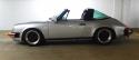 1980 SC Targa


