|
|
|
|
|
| Author |
|
|
Registered
Join Date: Aug 2018
Posts: 34
|
I connected A0-A7, RST, ALE, RXD (UART decode to HEX, @9600 baud), TXD (same decode) and PSNE but the decode didnt yield any sensible results. I sampled at 10 MHz and use ALE falling edge as trigger.
I can only use the decoder (I2C, PSI or UART) per channel, is your decoder different and (as the label suggests) decodes A0-A7 in parallel? first line reads 02 02 8B. |
||
 08-10-2025, 03:30 PM
|
|
|
Registered

|
So your code is LJMP 0x028B. You should see the EPROM being accessed at 0x0000, 0x0001, 0x0002, 0x028B, 0x028C and so forth. Disassemble the code to understand what it does and when it jumps.
I don’t know what software options you have but you need to sample 10 address lines (A0 - A9) to decode the LJMP destination. I can assign what lines will be considered for the decoding to hex. If your SW doesn’t allow that check if sigrok works with your analyzer hardware
__________________
1974 Targa 3.6, 2001 C4 (sold), 2019 GT3RS, 2000 ML430 I repair/rebuild Bosch CDI Boxes and Porsche Motronic DMEs Porsche "Hammer" or Porsche PST2, PIWIS III - I can help!! How about a NoBadDays DualChip for 964 or '95 993 |
||
|
08-10-2025, 03:42 PM
|
|
|
Registered
Join Date: Feb 2014
Location: Lomita, CA
Posts: 2,686
|
Sorry to see your efforts are now being wasted by reviewing the assembly language code!
Furthermore, the level of diagnosis required doesn't get any simpler for just a processor chip & a memory device, definitely not requiring a logic analyzer. The processor just runs in a very short loop waiting for timing sensor inputs.
__________________
Dave |
||
|
08-10-2025, 05:41 PM
|
|
|
Registered
|
Quote:
And you know this how? You clearly dont understand the working principle of these boxes else you would know that there are no timing sensor inputs required for the ICV signal to be generated. The OP is trying to diagnose if the processor is running code that initializes the DME or not. Why dont you make constructive comments that contribute like everyone else instead of criticizing and dissing others?
__________________
1974 Targa 3.6, 2001 C4 (sold), 2019 GT3RS, 2000 ML430 I repair/rebuild Bosch CDI Boxes and Porsche Motronic DMEs Porsche "Hammer" or Porsche PST2, PIWIS III - I can help!! How about a NoBadDays DualChip for 964 or '95 993 |
||
|
08-10-2025, 05:59 PM
|
|
|
Registered
Join Date: Feb 2014
Location: Lomita, CA
Posts: 2,686
|
Quote:
__________________
Dave Last edited by mysocal911; 08-10-2025 at 06:13 PM.. |
||
|
08-10-2025, 06:05 PM
|
|
|
Registered
|
Quote:
")
|
||
|
08-10-2025, 06:12 PM
|
|

|
|
Registered
Join Date: Feb 2014
Location: Lomita, CA
Posts: 2,686
|
Quote:
Again, it's really sad the OP's been lead in a direction over-complicating the troubleshooting process.
__________________
Dave |
||
|
08-10-2025, 07:30 PM
|
|
|
Registered
|
Loren,
Cant believe you have the audacity to peddle your lame company here again ! The OP wants to learn about the DME and instead of being helpful youre getting on your sad little soapbox begging for business. And why are you impersonating Dave? Oh wait havent you learned your lesson the first time around when you got banned here as Lorenfb, the real slim shady?  Man, youre a piece of work. I feel sorry for you. |
||
|
08-10-2025, 08:07 PM
|
|
|
Registered
Join Date: Aug 2018
Posts: 34
|
sigrok wont work with my LA hardware but I used their Pulseview software to decode a csv-export from the 'Labtool' software with the Pulseview included parallel decoder.
I captured A0-A9 plus the uC RST pin, ADC still out of circuit. Decoded A0-A9, only to find that an error is reported 2 cycles after A8 goes high. Since it's all 8-bits I reverted to decoding A0-A7 and no error messages. Why capture A8 and A9 (other than seeing it is not entirely dead)? I tried several methods of capturing a reset and by the looks of it managed several times (out of 30 or so...) but the hex dumps were all different from each other and none contained 02 02 8B, not even 02 02.  Let's consider the two possible outcomes of this exercise: 1. it jumps to the code in EEPROM but still I dont get the required ICV-signal 2. it doesnt jump to the code in EEPROM and that's why I don't get the required ICV-signal and keeps resetting. In case 1. I would replace EEPROM? In case 2. I would replace uC? Last edited by hardtailer; 08-11-2025 at 05:23 AM.. |
||
|
08-11-2025, 05:20 AM
|
|
|
Registered
Join Date: Feb 2014
Location: Lomita, CA
Posts: 2,686
|
Using two different 911 DME ECMs, tests were done without key ICs; EPROM, S705, S100, A/D. The 8051 address lines were active for 25ms then off for 12ms (reset).
Obviously there was no input to the ICV CMOS input pin 5. By only adding the EPROM, the CMOS ICV output functions. Therefore, there's only three possible failure points; 8051, EPROM, and/or the circuit board. A simple scope setup is all that's needed!
__________________
Dave |
||
|
08-11-2025, 11:32 AM
|
|
|
Registered
|
Guys, if your genuinely interested in helping the OP get to the bottom of his issue, might I suggest you work together [just this once] as I am sure by now the OP is close to pulling his hair out on this one!
Ant. 
__________________
"But instinct is something which transcends Knowledge We have undoubtedly certain finer fibres that enable us to perceive truths when logical deduction or any other wilful effort of the brain is futile" Nikola Tesla |
||
|
08-12-2025, 12:10 AM
|
|
|
Registered
|
OK, here comes a stupid question: since a 27C256 is used as EPROM in place of factory 27C64, what happens to pins 26 and 27? According to the factory schematic, they are both connected to +5V because they are unused, but with a 27C256, these pins become address bits A13 and A14.
I do understand that the code is stored in lower bytes and that the extra space available with the bigger 27C256 is not used, but shouldn't address bits A13 and A14 be set to zero and therefore connected to ground and not to +5V? Hardtailer, has this been addressed? (pun intended 
__________________
Gilles RoW 88 Carrera coupé |
||
|
08-12-2025, 03:22 AM
|
|

|
|
Registered
|
When using a 27c256 EPROM you put copies of the program into the extra space rather than modifying the PCB or jumpers.
__________________
1974 Targa 3.6, 2001 C4 (sold), 2019 GT3RS, 2000 ML430 I repair/rebuild Bosch CDI Boxes and Porsche Motronic DMEs Porsche "Hammer" or Porsche PST2, PIWIS III - I can help!! How about a NoBadDays DualChip for 964 or '95 993 |
||
|
08-12-2025, 04:36 AM
|
|
|
Registered
|
Try the following:
1. Set up your logic analyzer with a short sampling duration of no more than 1 a few milliseconds 2. Use a sampling rate of 5 Mhz or higher to get sufficient resolution, no external clock. Set the threshold to 2.5V 3. Capture A0 - A9, and RST. If possible also look at PSEN to help to pick when valid address is present. But it will be pretty obvious even without PSEN 4. Triger on the falling edge of the RST signal 5. Power up the DME. That should start the capture. In my logic analyzer I see RTS coming up to logic 1 (5V) and then go to logic 0 (0V). That is when the uC starts up. Shortly thereafter you see PSEN with a 1 Mhz pulse train. The address signals are valid on the falling edge of PSEN. You can see that the first byte is read in one machine cycle and the LJMP instruction takes 2 machine cycles to execute. That is why you see address 0x0002 being there twice.  One more thing. The original 8051 uses 12 clock cycles for one machine cycle. Each instruction takes one or multiple machine cycles to execute. If you are using a modern 8051 it might run more efficiently through the code and might make the logic trace look a bit different.
__________________
1974 Targa 3.6, 2001 C4 (sold), 2019 GT3RS, 2000 ML430 I repair/rebuild Bosch CDI Boxes and Porsche Motronic DMEs Porsche "Hammer" or Porsche PST2, PIWIS III - I can help!! How about a NoBadDays DualChip for 964 or '95 993 |
||
|
08-12-2025, 06:19 AM
|
|
|
Registered
Join Date: Aug 2018
Posts: 34
|
Many thanks, Ingo! Greatly appreciate your support.
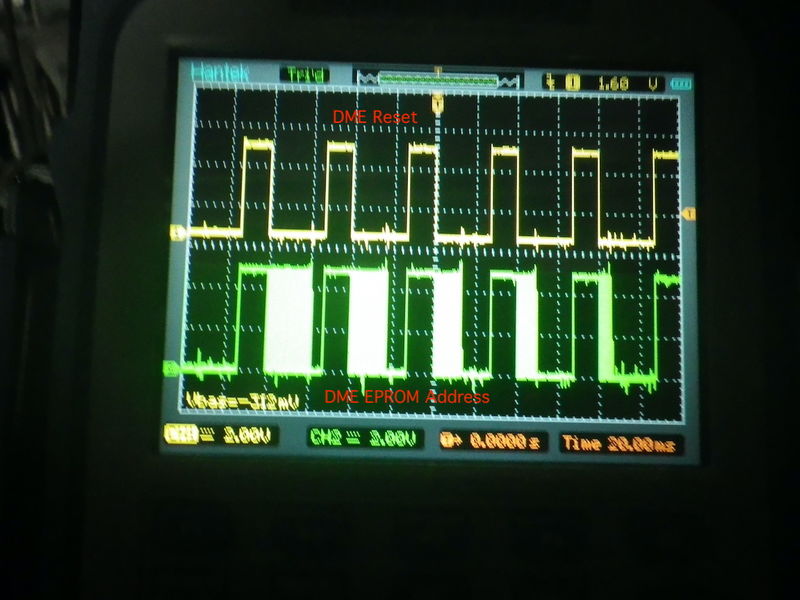
Adding PSEN and ALE (as analog signals) helped to identify beyond doubt the start up of uC. I still get differing captures but the differences seem to be 'interjections' of FF and some other hex numbers. Or is this just wishful thinking? Have a look please at two different captures and the respective decoded beginnings. At the beginning of the 2nd full cycle of ALE/33.2 us I get the 8B at adress 0002  The mouse pointer is at 8B   ========================================== Different capture:    How does this look with regards to the uC starting the commands in the EEPROM? These are the corresponding HEX numbers inside the EEPROM 00 01 02 03 04 05 06 07 08 09 0A 0B 0C 0D 0E 0F 00000000 02 02 8B C2 8B 41 2D FF FF FF FF D2 90 C2 0A 32 ..?Â?A-....Ò?Â.2 00000010 FF FF FF 05 36 30 1C 44 32 FF FF D5 2A 13 11 22 ....60.D2..Õ*.." 00000020 41 8B 32 10 99 08 A8 99 C2 9B 86 99 C2 98 C2 89 A?2.?.¨?Â???Â?Â? 00000030 32 10 94 0E D2 94 85 43 8D 85 42 8B 20 1C 02 C2 2.?.Ò??C??B? .. 00000040 89 32 85 47 8D 85 46 8B 85 45 43 85 44 42 85 36 ?2?G??F??EC?DB?6 00000050 37 75 36 00 D2 17 20 1C 02 C2 89 32 D5 2B 31 D5 7u6.Ò. ..Â?2Õ+1Õ 00000060 2D 03 12 10 00 53 A8 EA 11 AA 30 8B FD 05 36 C2 -....S¨ê.ª0?ý.6 00000070 8B D5 2D 03 12 10 00 20 10 0D 20 B3 03 30 8B FA ?Õ-.... .. ³.0?ú 00000080 B2 91 20 8B 07 01 82 30 8B FD B2 91 D2 AA 01 AB ²? ?..?0?ý²?Òª.« 00000090 D5 2D 17 12 10 00 53 A8 EE 11 AA C0 E0 C0 D0 C0 Õ-....S¨î.ªÀàÀÐÀ 000000A0 83 C0 82 C0 F0 90 21 A0 21 58 32 C0 E0 C0 D0 C0 ?À?Àð?!*!X2ÀàÀÐÀ 000000B0 83 C0 82 C0 F0 90 21 A0 20 91 13 E4 A2 10 35 30 ?À?Àð?!* ?.ä¢.50 000000C0 13 14 92 10 C2 AA 25 2B F5 2B D2 AA 21 58 E4 A2 ..?.ª%+õ+Òª!Xä¢ 000000D0 10 35 33 95 31 C3 95 59 C3 95 2F 40 05 B4 12 00 .53?1Ã?YÃ?/@.´.. 000000E0 50 0A C3 94 12 25 59 F5 59 74 12 C3 13 14 92 10 P.Ã?.%YõYt.Ã..?. 000000F0 C2 AA 25 2B F5 2B D2 AA 74 03 25 35 93 C2 AA 25 ª%+õ+Òªt.%5?ª% 00000100 2D F5 2D D2 AA 51 5A C2 89 D2 A8 75 D0 18 02 10 -õ-ÒªQZÂ?Ò¨uÐ... 00000110 29 D5 34 44 75 F0 2C 20 16 0F 75 F0 2A 20 15 09 )Õ4Duð, ..uð* .. 00000120 75 F0 28 20 14 03 75 F0 26 E5 F0 93 F5 34 05 F0 uð( ..uð&åð?õ4.ð 00000130 E5 F0 93 F5 F0 E5 32 C3 95 31 C3 30 E7 0E F4 04 åð?õðå2Ã?1Ã0ç.ô. 00000140 95 F0 E5 32 40 10 E5 31 95 F0 21 56 95 F0 E5 32 ?ðå2@.å1?ð!V?ðå2 00000150 40 04 E5 31 25 F0 F5 31 C2 89 D2 A8 10 37 02 41 @.å1%ðõ1Â?Ò¨.7.A 00000160 22 75 D0 18 74 01 93 05 35 B5 35 0F 75 35 00 90 "uÐ.t.?.5µ5.u5.? 00000170 00 00 F0 F0 F0 F0 90 21 A0 21 A3 20 1A 25 10 0F ..ðððð?!*!£ .%.. 00000180 02 41 22 75 F0 40 E5 4E A4 FE AF F0 30 0A 02 80 .A"uð@åN¤þ¯ð0..? 00000190 03 02 01 F8 C2 8C C3 E5 8A 9E F5 8A E5 8C 9F F5 ...øÂ?Ãå??õ?å??õ 000001A0 8C 41 0D C3 74 11 93 95 37 72 1D 40 6E AE 4C AF ?A.Ãt.??7r.@n®L¯ 000001B0 4D 02 10 2C 20 1A 41 30 0D 2D E5 4F B4 10 00 40 M.., .A0.-åO´..@ 000001C0 0C C2 0D 30 16 05 C2 16 75 34 01 21 E7 90 21 80 .Â.0..Â.u4.!ç?!? @Gilles: the 27C256 has the same contents as a 27C128 in both its upper and lower half of the adresses, just like Ingo wrote. Last edited by hardtailer; 08-12-2025 at 01:35 PM.. |
||
|
08-12-2025, 01:22 PM
|
|
|
Registered
|
I haven't gone through all of your data but here are a couple of observations:
PSEN and ALE look different in level. Are you using different probes or is there something wrong with PSEN? Why are there spikes on the RST line? Not sure how your software analyzes the data and translates it into HEX. Looks like it generates numbers when the address is not valid. But A8 and A9 do the expected thing soon after the reset telling you there is a jump executed. You keep mentioning an EEPROM. What exact memory chip are you using and have you checked that it works by swapping it into a different box? And then confirm that the jumper settings on both boxes are identical. The logic PCB has several jumpers near the EPROM socket that configure it for various EPROM sizes. This affects how the higher address lines A12, A11 and some other signals are routed to the socket. All this applies to the 911 3.2 DME but might also be the case for your version. While I disagree with Loren's social skills he has a valid point in that you only need clock, a working latch and the EPROM with proper contents for the 8051 to begin producing a square wave on P1.4 (pin 5). The early startup appears good so maybe the 8051 doesn't see the upper 4k of the EPROM contents?
__________________
1974 Targa 3.6, 2001 C4 (sold), 2019 GT3RS, 2000 ML430 I repair/rebuild Bosch CDI Boxes and Porsche Motronic DMEs Porsche "Hammer" or Porsche PST2, PIWIS III - I can help!! How about a NoBadDays DualChip for 964 or '95 993 |
||
|
08-12-2025, 01:47 PM
|
|
|
Registered
Join Date: Feb 2014
Location: Lomita, CA
Posts: 2,686
|
Quote:
Maybe there's a lack of comprehension of what has been posted? Quote:
 A good 8051 should output the correct EPROM addresses! There's NO need to disassemble the Hex code. You know you can dump the hex & display alpha characters? Even the old DOS system could dump & display the alpha characters. Post 83; Quote:
Remember, you can always buy a 944 DME and use its logic board with a good BMW M3 EPROM copy, or a Dinan chip.
__________________
Dave Last edited by mysocal911; 08-12-2025 at 03:50 PM.. |
|||
|
08-12-2025, 03:05 PM
|
|
|
Registered
Join Date: Aug 2018
Posts: 34
|
Probes (1:1) are identical on A0 and A1. I needed to reduce the scale to 0.2V/div for PSEN to see what is shown. I didn't think anything of it but now you mention it, psen should be between 0 and 5V right?
Can't tell you why there are spikes on rst line. The eprom (my bad for calling it eeprom) is a nmc27c256bq and has worked in the past but I haven't used it in the car recently. The jumpers are set identically and correct (on both DME's) for use with this eprom. Dave! Good to have you too here! Indeed, I do not always understand what you're implying with an answer that is just one or two sentences long, as my knowledge is too limited. The thing is, I'm waiting for parts to arrive and in the mean time I'm posting the results to the suggested next steps. Unfortunately each result leads to my new questions. I understand that it is hard to answer them, not watching me and therefore no way of recognising I'm doing something wrong in the process but it would be great to receive an explanation nonetheless. I agree there is no need to rewrite any code, I'm just curious to see if I can use the logic analyzer to identify what parts exactly needs to be replaced. Based on the almost not existing PSEN signal, I reckon it is at least the eprom. Can and will you confirm? Surely you remember that I have replaced all ICs (and have mentioned it earlier) for brand new ones as well as the eprom from the working DME but even immediately after I still was not getting the ICV output on uC pin 5. Last edited by hardtailer; 08-12-2025 at 04:09 PM.. |
||
|
08-12-2025, 03:54 PM
|
|
|
Registered
Join Date: Feb 2014
Location: Lomita, CA
Posts: 2,686
|
It's this simple:
1. Don't waste any more time with your logic analyzer & EPROM dumps. 2. Get a known good 8051 & 8K EPROM chips, tested in a good DME. 3. Remove all chips except the quad comparator (reset signal) of the NOK board. 4. Attach good sockets for the 8051 & EPROM. 5. Install the good 8051 & 8K EPROM. 6. Power the DME with 12V & ground. With a good 8K EPROM, a good 8051 will NOT be reset, and should send the ICV signal to pin 5 of the CMOS driver IC. If not, you have a bad PCB! Remember: No need for the A/D conv and the 8 bit latch either, as the 8051 will just receive all zeros for requested analog data, e.g. temp/AFM. The troubleshooting doesn't get any simpler than that!
__________________
Dave Last edited by mysocal911; 08-12-2025 at 10:39 PM.. |
||
|
08-12-2025, 04:12 PM
|
|
|
Registered
|
Quote:
__________________
1974 Targa 3.6, 2001 C4 (sold), 2019 GT3RS, 2000 ML430 I repair/rebuild Bosch CDI Boxes and Porsche Motronic DMEs Porsche "Hammer" or Porsche PST2, PIWIS III - I can help!! How about a NoBadDays DualChip for 964 or '95 993 |
||
|
08-12-2025, 07:12 PM
|
|


 1974 Porsche 911 Targa 3.6
 1985 Porsche 911 3.2 Carrera Sport
 88 Carrera coupé
