|
|
|
|
|
| Author |
|
|
Kartoffelkopf

|
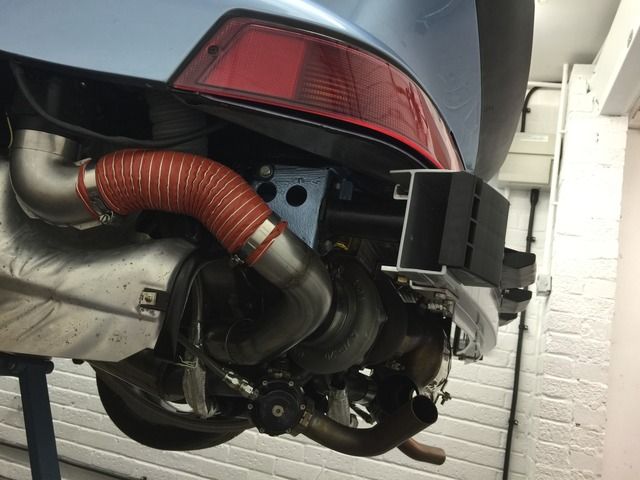
Some more evening progress; I got the cold air hoses and pipework fitted; as I'm running a non-stock set of headers, the pipework for the heating is also very non-stock, it doesn't use a couple of the metal elbows for example. All went back together ok, just needed some re-alignment of the blowers to get the orientation correct....
  Another job I've been keen to cross off the list is to give the rear lamp recesses a clean and polish; they were "socially" cleaned a few years ago, but another clean-up and coat of polish never hurt. Then time to fit my new lamps and rear reflector; I may be a little previous in doing this, but hey a good morale booster as it looks even more finished now! (Engine lid needs alignment) 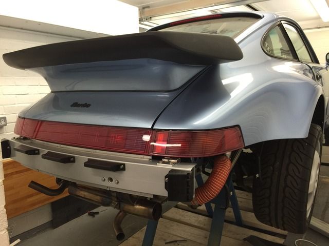 I've just noticed that the under tray for the gearbox looks to be the wrong part! Something I saw the other week was that one of the tangs that clips under the tunnel cover has been snapped off at some point (not by me), so cross referencing the part number vs the PET and I see that there's a specific 965 part (965 504 129 01); the one I have is for a manual Carrera (964 504 129 02). Terrific.....that's another $430....time to see how friendly my OPC can be ") Anyway, not going to dwell on that, the car came with this part on, so worst case it can go back on again temporarily. A good weekends work, time for supper and catchup on last weeks MotoGP races. Last edited by Spenny_b; 06-21-2015 at 05:02 PM.. |
||
 06-21-2015, 02:10 PM
|
|
|
Kartoffelkopf
|
Ok, the clutch line....argghh! the bloody clutch line.....
Right, in the spirit of this maybe being useful to somebody in the future, and it not being an obvious answer, let me precis my findings so far, which I've already posted in my thread on Rennlist..... The problem (can't remember if I've already mentioned this...) was that I damaged the original complex bended line that, on RHD cars, connects to a chassis line that runs down the transmission tunnel and stops about where the tail of the gearbox sits, it then crosses the transmission tunnel and snakes its way up near to the slave cylinder. I shouldve been more attentive when Dad and I reinstalled the engine/box a few months ago; the tail of the box snagged the line and kinked it.  Then there's a rubber line that connects up to the slave cylinder.... 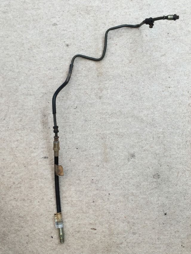 Okay, that sounds easy enough, eh? Just look-up in the PET the correct part and order one?....Kind-of....not. The PET is described thus: 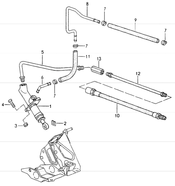 ...which got me scratching my head a little; Item 13 is the Female-Female adapter which I'd just got re-plated. Ok, then Item 12 must be the bended pipe, as it then interfaces into the rubber line....so why is it showing as a straight length? I spoke with OPC Tonbridge to try and confirm whether Porsche ship it like this, or if it comes pre-bent. Frankly, I didn't want to go and buy an 8mm pipe bender, then mess about trying to bend it accurately to re-install into the chassis clips. The answer back was that it comes pre-formed. Great. Order one, only £19. Then I received this: 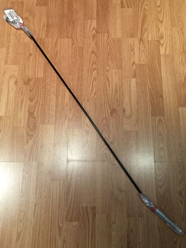 ...which in fairness, does look pretty similar to the diagram (it has a pre-bent "hook" under the polythene wraps). Oh great. Not only is it 50% too long, but looks nothing like what I was hoping for. Plan B....lets return this and make one single piece line to replace the steel and rubber length, using teflon -4AN hosing. Next challenge is that Porsche decided to use M14 fittings; they're hard to come by to say the least...at least, they are with the correct convex/concave, female/male combination...believe me, I've tried. My usual supplier, Think Automotive didn't have anything, so I thought I'd make my life easier and order one from a specialist car/motorbike hose manufacturer. Apparently this was possible, but a month later and numerous chases, I received completely the wrong part, fittings at both ends being the opposite of what was needed. Nice try, but no cigar. Upon further clarification, apparently the parts I *would* need are "just not available". Hmmm. Alright, so, back to the part I ordered from Porsche - can I modify this? i.e. shorten it, re-flare a mating face and then form the bends? Well, I was pointed in the direction of a hydraulics hose manufacturer local to me, but after a 30mile jaunt, they don't do automotive stuff. By the way, this isn't a standard SAE single flare, for which I could buy one of many DIY pipe flaring tools.... 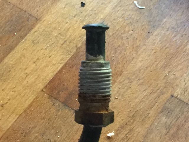 By doing some Googling, this is a DIN flare, with the square shoulder abutting the M14 ferrule. My next plan was to then make my own single-piece length (Rob, I can hear you cheering from here...) running from master to slave cylinder. Plan was to use 2x metric adapters, then 2x -4AN fittings and -4AN teflon hose. There looks to be a metric adapter from Goodridge thats described as this, however, without seeing a tech drawing and verifying seat angles, I can't be sure it's correct. And at £23 each for steel/plated examples, not cheap enough to take a punt on. So, I thought I'd make my own! I have both the imperial and M14 dies, I have the ally hex stock....easy enough..... When I crawled under the car to start measuring the hose length required, it all became apparent with regards to the Porsche parts....let me explain.... If you look at diagram 702-08 (above), then refer to the table, right at the bottom.... 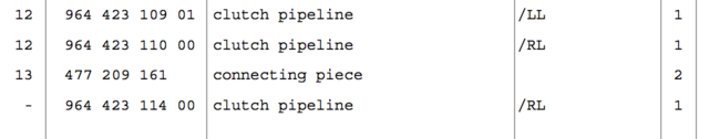 ....there's a description for an item that has no item number, nor is it shown in the diagram - it's a "hidden part" - number 964 423 114 00, for RHD models only (which makes sense, as this pipe crosses across the transmission tunnel, clearly not required for LHD cars). Arggghhhh!!! Hidden-bloody-parts!! Why, oh why, oh why....? The part I've bought is the middle section of the line; where the rigid line fixes to the master cylinder in the footwell, it then exits the cabin via a very shallow angled hole, right above the power steering lines, hence why I didn't immediately see it. This is right at the front of the transmission tunnel. "My" line then attaches to this using another F-F hex adapter, goes up the tunnel about 125cm to the second F-F hex adapter, where it then attaches to the wiggly pipe that I now need. So, the line from master cylinder to slave is composed of 4 parts not 3 as indicated in the PET; 3x rigid lines + the flexi black hose. The PET is therefore not wrong, but very much incomplete, insomuch that the wiggly pipe is just not shown! Anyway, he's ordering one from Germany so we can have a look-see...about £53 and 2 days away as I type. So, that's a long write-up for not a lot of part content....but hoping that somebody in the future will benefit from this, as/when their original lines need replacing. |
||
|
06-25-2015, 02:57 AM
|
|
|
Registered

Join Date: Mar 2005
Location: Phoenix, AZ
Posts: 2,862
|
We all love Porsche's cars, but their parts & technical documentation is woefully lacking in contrast to other major manufacturers (ex: BMW, Nissan, etc.)
Glad that got figured out. Excited for you to get driving!
__________________
Chris Carroll TurboKraft, Inc. Tel. 480.969.0911 email: info@turbokraft.com http://www.facebook.com/TurboKraft - http://www.instagram.com/TurboKraft |
||
|
06-25-2015, 10:51 AM
|
|
|
Kartoffelkopf
|
Haha, yeah I was so relieved to have nailed it - I hope - that I needed to get findings down on paper, just in case!
My next consideration is around what we discussed a couple of years ago and whether to (...while I'm at it) buy a new clutch master cylinder and also to modify the clutch pedal with the 3.6T setup. I've printed off the 2x PET diagrams to compare the parts required; I'll cost it up over the next few days and see if I want to go for it, before I fill and bleed the clutch system. If I do replace the m/c, then thats the whole system swapped (I had the occasional hanging clutch pedal before), so then the only thing left to change is the kinematic plate, unless that forms part of the 3.6 spring/cam assist assembly. Last edited by Spenny_b; 06-25-2015 at 11:42 AM.. |
||
|
06-25-2015, 11:40 AM
|
|
|
Kartoffelkopf
|
Quick pre-weekend update.....
The fabricated bumper mounts have now been powder coated; as always, a superb job by Windridge Coatings.  The thickness of the coating - although certainly not "thick" - has made the fit onto the beam a very snug fit; the retaining L sections for the captive block nut have needed a little gentle persuasion to open them up a smidge, next job is to fasten them for the final time, then fit the heat reflective shield onto the beam. More pics tomorrow. On another subject, I've had a few discussions with Lifeline, the fire extinguisher guys. Turns out their techie, Dave, is another Porsche owner (944 Turbo), so we had a good chat about the project, and has given some great advice with regards to installation and use of the nozzles. I'd got into analysis-paralysis mode with thinking about where to locate each of the 6 nozzles you get with the kit. Long story short, as I'm going to be also buying a handheld unit, we're not using any nozzles in the cabin, and by the time you know about any fire in the frunk, chances are it's way past being able to do much about it, with the fuel cell there. So, I'm going to use all 6 nozzles on the engine bay; 2 on the underside at the rear near the turbo and oil catch tank, then 4 in the upper half of the engine bay, one per corner. Now I need to fabricate some brackets to mount them with, then route the pipe work. Whilst chatting, we mulled over the idea of installing the bottle externally to the cabin, in the huge void between the transmission tunnel and the frunk recess. 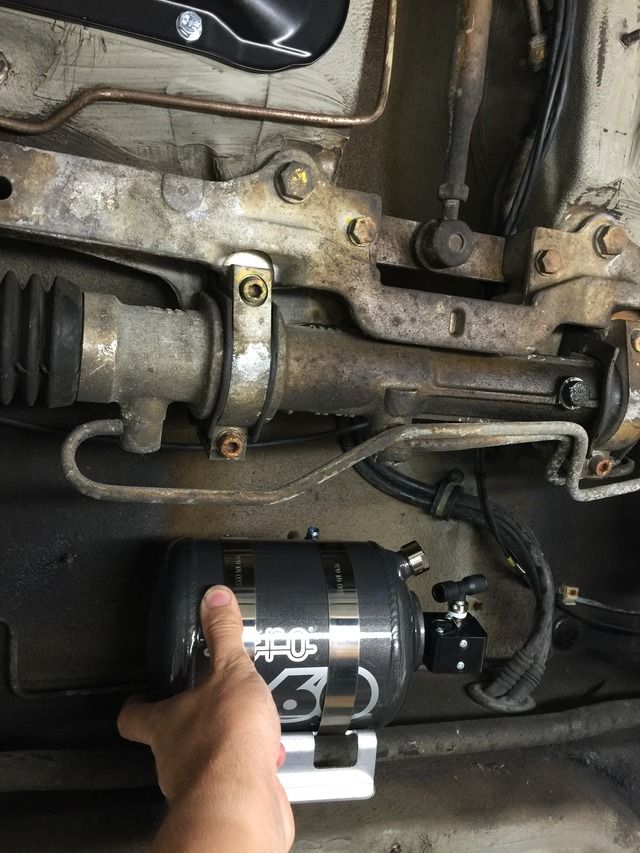 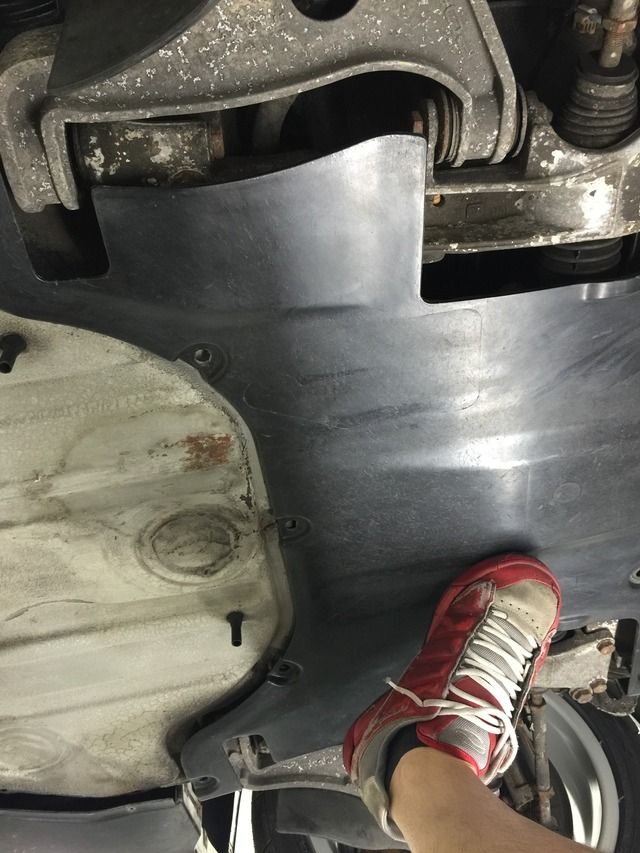 This would've been very convenient; the line could've gone straight down the tunnel undisturbed, however, the plastic cover that installs under there is just a bit too open to ingress, so Daves advice was to play it safe and go back to Plan A, fitting it inside the cabin at the top of the passenger footwell, tucked up under the dash. |
||
|
06-26-2015, 07:02 PM
|
|
|
Kartoffelkopf
|
The Oil/Air Separator Tank.....
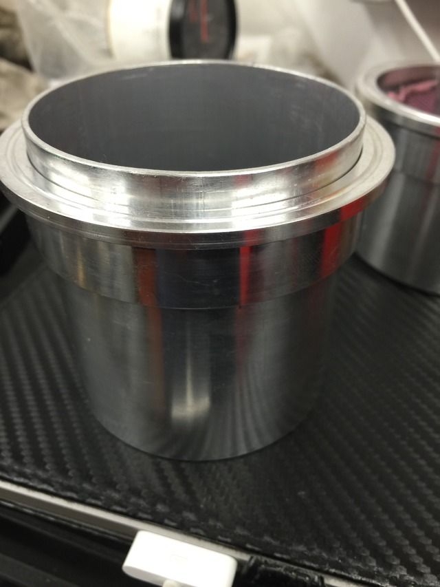
I started preparing all the component parts for the oil separator tank last night, and have just finished for the evening (current 3.30am as I type this…), having now made all the components that Pete is going to weld up for me later this morning. Each half of the cylinder has been made; really nice fit into the collar for the V-band fitting.
 The lid and base are cut to size with holes drilled for the weld-on bosses. I did try to mimic the stock 930 part, where the inlet to the tank feeds in tangentially (Chris's word!), effectively swirling the "dirty" air against the tank wall. However, due to the mounting location and the position of the inlet pipe, I just couldn't see how to achieve this with the fittings I have. So, after kicking myself up the arse to get on with it, decided on this design to start with and see how it goes. If I see evidence of oil in the inlet tract as part of my routine "new build" checks, then I'll rethink and redesign. 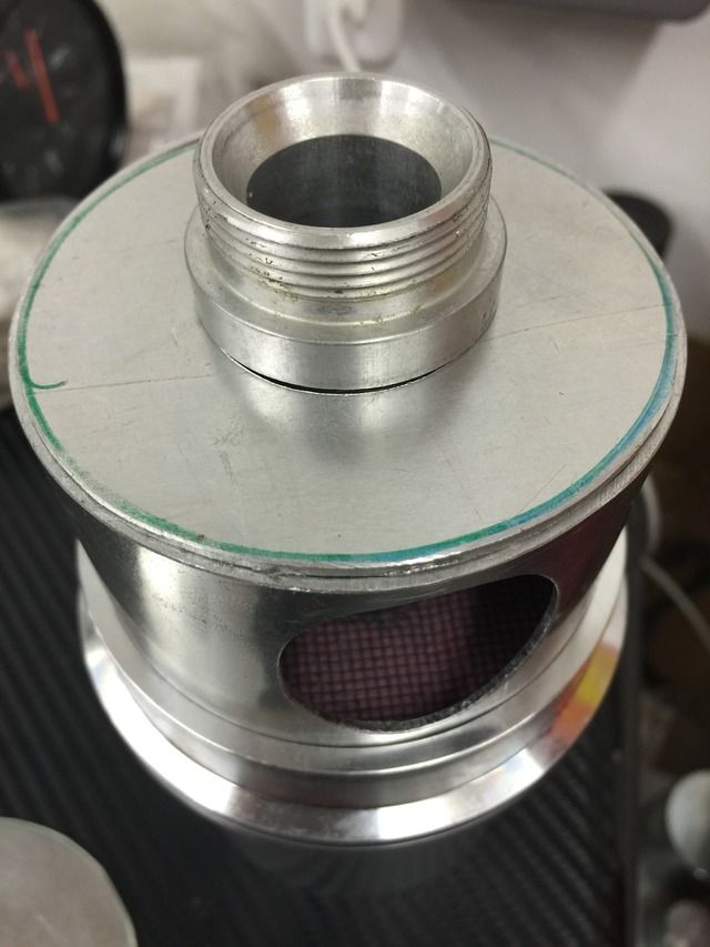 I was going to use some foam filtration material, as used on my air filter, then sandwich it with stainless mesh. However, I do know they succumb to age. I happened to have stored in my loft an old filter from the Westfield - it was a little bit tired looking, hence I replaced it, but functionally it was fine and too good to throw away. I retrieved it hoping to use it for this project but after 2-3yrs in storage, it crumbled and literally fell apart as soon as I got it out of the box. Now, for the air filter, I can keep an eye on things externally but for a filtration layer thats contained in the tank, out of sight, I don't want to risk this crumbling and then getting ingested post-air filter into the turbo. So, a K&N style material seems like a good bet, and was available off the shelf from my local parts store. A bit extravagant perhaps, using a $60 part to then chop it up....could've had a look on eBay for a cheap used one, but wanted it straight away for the weekend.  My first attempt took bloody hours, albeit some of that time was cutting off the rubber gasket surround from the stock unit. Anyway it failed! What I thought would be a good idea, would be to retain as much filter as possible, keeping the original folded shape, and cutting a disc the same ID as the tank, then trying to cut a neat 1" hole in the middle for the inlet pipe to pass through. Ultimately, it looked a dogs-dinner, and didn't fit tightly enough to the outer wall to seal anything. 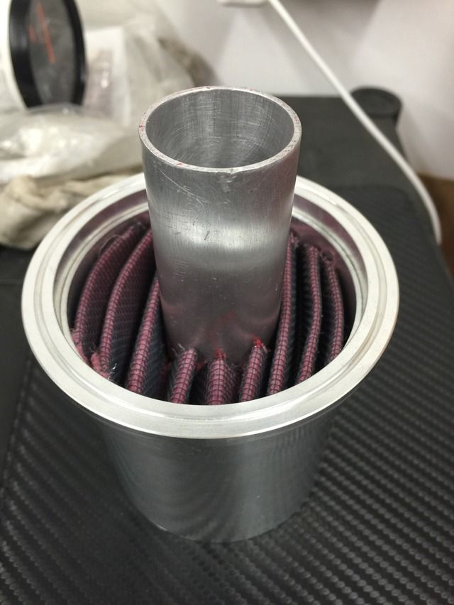 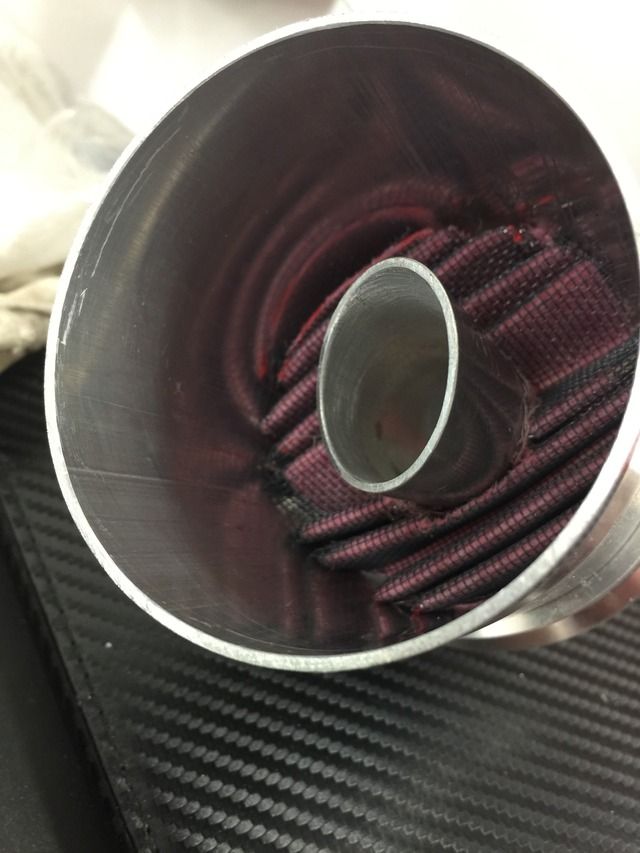 Attempt #2 was to then unfold the material and cut a disc (a LOT easier this way), but what I hadn't thought about was the fact that it would fall apart, the two layers of metal mesh not retained and thus not keeping the filter material in place. Ok, version 3, easy fix, cut another disc that 10mm larger in OD, along 5mm all the way around to fold back on itself in a crimp fashion. Perfect....this can now sit in the gap where the 3" tube sits in the V-band connections. If I then protrude the lower tank pipe through its connection (see first pic above), when the 2 halves are mated, the protrusion will trap the filter in place. All assuming that tomorrows welding doesn't distort the pipework.... 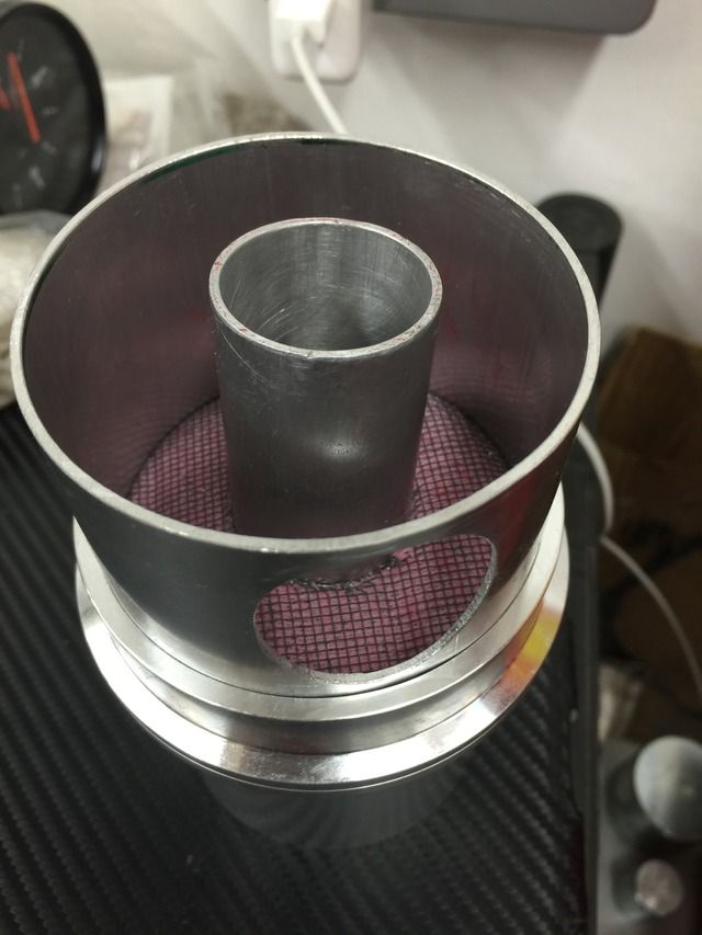 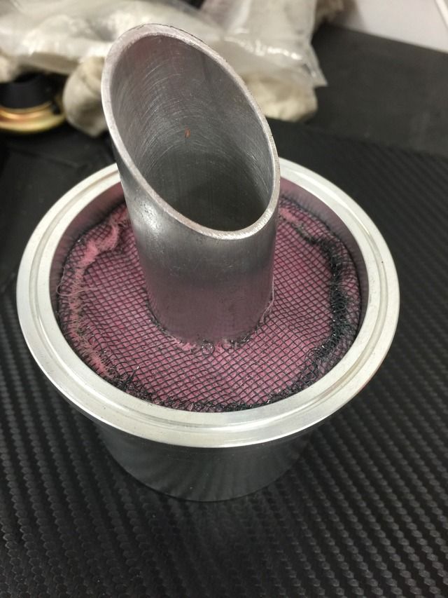  I may well make a second filter in the same way, but fit it inverted, so that both raw edges are inwards. I could then be trick and try using some Tiger Seal to join them and form a rubber gasket....we'll see. Last edited by Spenny_b; 06-26-2015 at 07:35 PM.. |
||
|
06-26-2015, 07:22 PM
|
|

|
|
Registered
Join Date: Mar 2005
Location: Phoenix, AZ
Posts: 2,862
|
So what's the problem locating by the steering rack?
__________________
Chris Carroll TurboKraft, Inc. Tel. 480.969.0911 email: info@turbokraft.com http://www.facebook.com/TurboKraft - http://www.instagram.com/TurboKraft |
||
|
06-26-2015, 07:27 PM
|
|
|
Kartoffelkopf
|
Quote:
|
||
|
06-26-2015, 07:31 PM
|
|
|
Registered
Join Date: Mar 2005
Location: Phoenix, AZ
Posts: 2,862
|
Quote:
__________________
Chris Carroll TurboKraft, Inc. Tel. 480.969.0911 email: info@turbokraft.com http://www.facebook.com/TurboKraft - http://www.instagram.com/TurboKraft |
||
|
06-27-2015, 08:19 AM
|
|
|
Kartoffelkopf
|
Yep, that was my thinking too Chris - he did also say that if it were hidden, the chances are you also wouldn't remember to check the cylinder condition as part of your "pre-flight check", i.e. that the sight gauge is in the green.
Finished the tank today, really chuffed with it, will post some pics later; Brother and I are watching the McQueen Le Mans movie at the moment, reliving the atmosphere from a few weekends ago! |
||
|
06-27-2015, 12:46 PM
|
|
|
Kartoffelkopf
|
Well I don't quite know how I'm still awake on 3hrs sleep, but thought I'd quickly post another update of todays progress.
Really good days work, not stopped apart from eventually kicking back with my Brother and making use of the lovely summer weather, having a BBQ, beer and watching Le Mans! The 38mm spanner arrived today, so I can now get the oil return line from the engine to the tank re-aligned and tightened. The stainless hose clips for the "hot" hoses from the exhaust to the rear blowers have arrived, along with the Mikalor T-bolt clamps to fasten the pipework to the main system. The "T" section silicon hose was the final part to arrive today, which I'm going to use on the inlet pipework to then accommodate the tank breather. Speaking of which....some photos of the finished tank which Lewis has done a sterling job of welding. A couple of hours over at Pete's place in Deal this morning (always great to catchup and natter about bikes, cars, trackdays, anything fast) for them to make sense of the mass of parts I walked in with! It's turned out exactly as planned, very pleased indeed. I spent this afternoon doing my usual thing of filing back and sanding the welds, in preparation for it to be either anodised or powder coated, although have to say that both Pete and I are almost of the opinion that it'd look good left as-is. 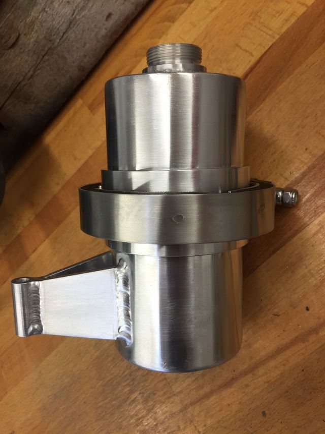 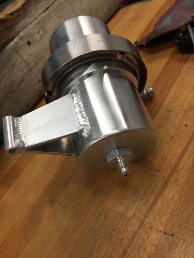 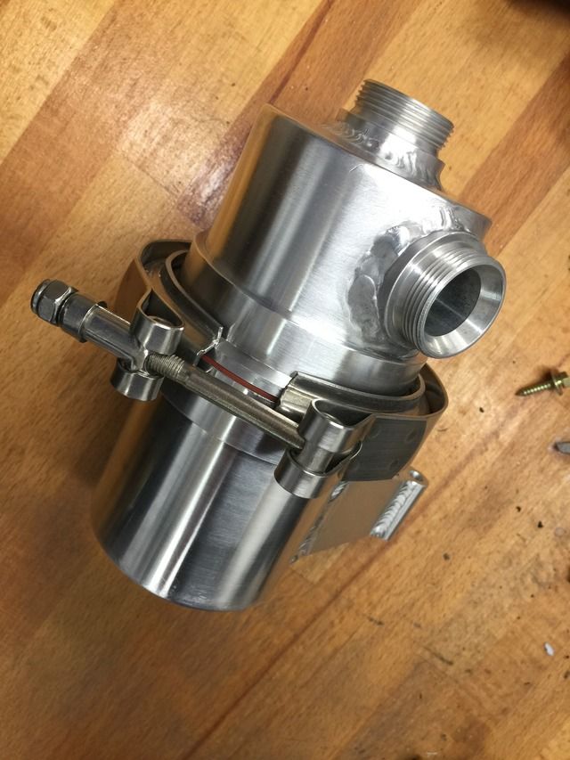 I remembered after last nights update, that I also needed to put in a couple of baffles; nothing too complicated or even accurate, just something that gets in the way of the venting air to try and separate the oil using a pair of "C" plates overlapping. The inlet pipe installs down the middle ---> 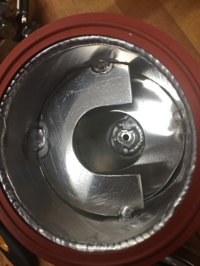 Next job is to shorten the rear/right pillar that supports the intercooler mounting plate. This is approx 10mm diameter with M6 timesert threads; I have a spare (that I made fractionally too short), which is anodised and can now be made even shorter to allow for the mounting system you see in the above photos. Doing it this was, I can then pivot it around to the perfect location (I hope) before final tightening, and means I don't then have to drill into the chassis for an additional fixing position. Right, off into the workshop for more tinkering..... Last edited by Spenny_b; 06-27-2015 at 02:40 PM.. |
||
|
06-27-2015, 02:32 PM
|
|
|
Kartoffelkopf
|
Some pretty good Sunday progress.....undertaken with the 6hrs of Watkins Glen being played in the background.
The rear bumper (the never ending sub-project) is a bit further along. Mounting bracket now finally mounted with the stainless hardware and zinc grease to ensure it'll come apart again in the future. 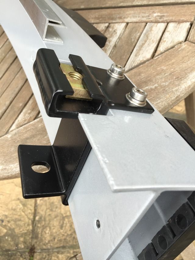  The heat shield is also now on, plus some sundry hardware items. Just need the bodywork back from Shaun now (Tuesday on the way home from work, hopefully) The oil return line is now finally installed, both ends tightened, the line correctly routed and fastened in place on the crankcase and the chassis. The middle of the line runs very close to the 4-5-6- header, so I've use a section of heat protective sleeving and fastened it just in that are, using stainless lock wire to hold it in position. Stupidly, I bought the sleeving ages ago but for some unexplained reason, forgot to put it on the hose before fitting the -16 couplings.....and frankly, I'm not about to undo them again to fit the sleeve; they were not easy to fit. 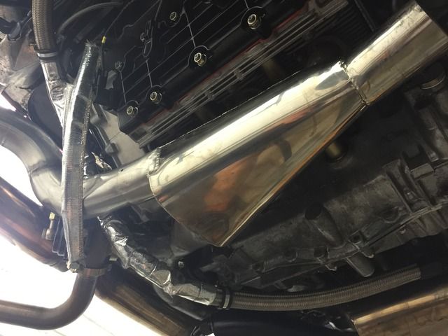  Now the all the lines are fitted and tightened, I've filled the tank with oil; 8.5qts so far, but will of course take more one the engine's spun over and then once the thermostat opens and fills the cooler. Lastly, the rear pillar of the intercooler mount plate has now be swapped for the shorter one which I turned down to accommodate the new OAS tank.... 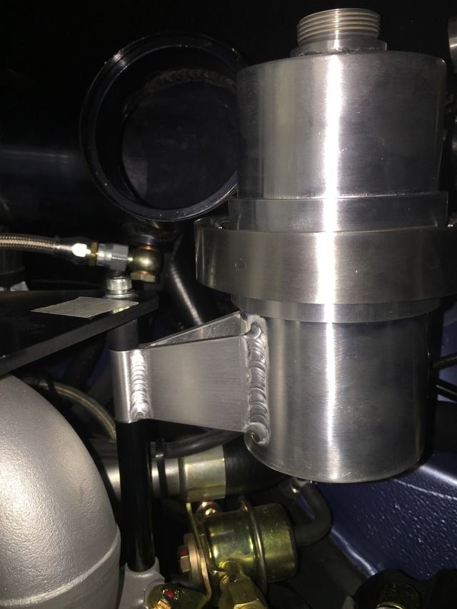 The cold side charge pipe is now back off, so that I could get the air filter in place - some careful manoeuvring required to avoid tearing the foam. New "T" silicone hose is now on the inlet tract, and I'll be trial fitting this later. I was hoping to fit the last pair of ducting pipes onto the rear blowers but have just discovered that the supplier have sent me the wrong diameter of hosing. Again. I've received 70mm, I need 76mm. Also, the Mikalor clamps I ordered for the 68mm pipework are also wrong - my fault, 68mm is borderline between 2 sizes offered, and as a result they don't clamp down small enough. Grrrr. Plagued by irritating issues that just haemorrhage time, this really is starting to wear thin now. Plan for the coming week are to:
|
||
|
06-28-2015, 01:17 PM
|
|
|
Kartoffelkopf
|
Dammit....just failed on the first bullet point.
F******* car. |
||
|
06-28-2015, 04:24 PM
|
|
|
Registered User
Join Date: Apr 2012
Location: London, UK
Posts: 58
|
Quote:
__________________
996 GT2 |
||
|
06-29-2015, 08:07 AM
|
|
|
Kartoffelkopf
|
That's not a bad idea Fred....I may do better work facing the other direction!
(oh...you mean bottom-to-top?....yep, that makes sense as well) 
|
||
|
06-29-2015, 11:44 AM
|
|
|
Kartoffelkopf
|
Only a very minor and brief update this evening.....
Extinguisher bracket back from powder coating (I'm being a complete part-tart).....just in case I do have to fit inside the cabin, at least it'll be more discreet than the stock naked aluminium, against the black carpeting. 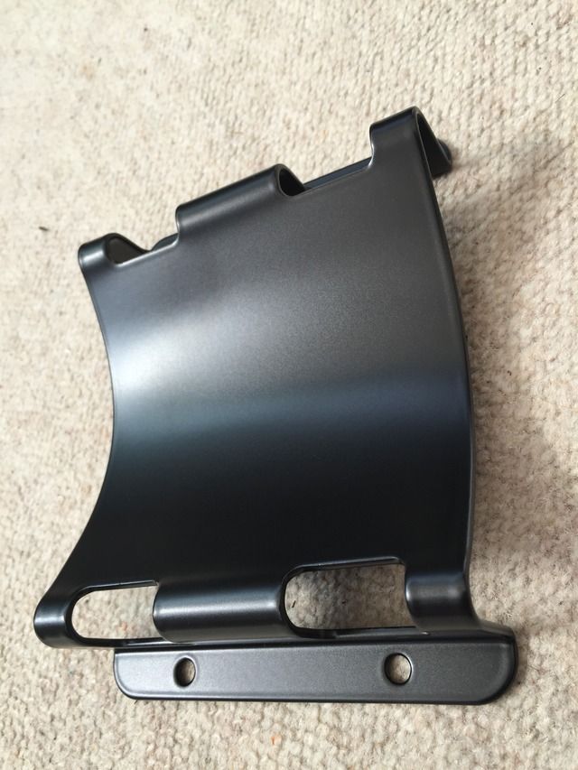 Did a swap, dropped the OAS tank off with them once I'd masked all the mating faces and threads. Hoping this will be done in the next day or so. Last night - before losing the will - I was playing around with the oil drain line from the OAS tank. Made the line up using -4AN and a 45º + a 90º fitting. The good part about having such long protracted projects is that you tend to acquire loads of parts....a rummage around my Fluid Couplings storage drawer and I found exactly what I needed; a -4AN fitting that I can then fit into the crankcase breather chimney, substituting it for the previous blanking plug. This is where any oil will drain back into. I can't believe how much longer everything takes to fit, now that the engine's back in the car - JHC.....10x longer, I swear. And I really did swear. 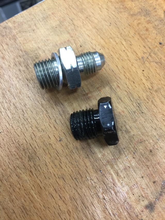 Tomorrow I'm working from our office near to Think Auto, so I'll nip out over lunch and get them to swage on the hosing for the OAS tank fittings. Just need to make some ally adapters to interface 25mm to 20mm and I'll be done. Clutch line and some sundry bumper support bracket fittings should also be ready for collection from OPC Tonbridge en-route home in the evening. Having an evening off tonight, got some work that needs doing before the end of quarter (tomorrow)....probably no bad thing to have a day away. |
||
|
06-29-2015, 01:43 PM
|
|
|
Registered User
Join Date: Apr 2012
Location: London, UK
Posts: 58
|
Quote:
 Try both, see what works best for YOU!
__________________
996 GT2 |
||
|
07-01-2015, 05:02 AM
|
|
|
Kartoffelkopf
|
Midweek update....well, almost...
Been busy doing work work most evenings this week, swatting for an exam this afternoon (passed...yay me) so not much opportunity to get onto car stuff. However... I now have the new clutch line - hallelujah! Was disappointed to find that my old one wasn't *that* buckled after all, when compared to the new one....but the places where it was damaged was on the 90º bends where the inside radius had deformed inwards; no retrieving that. 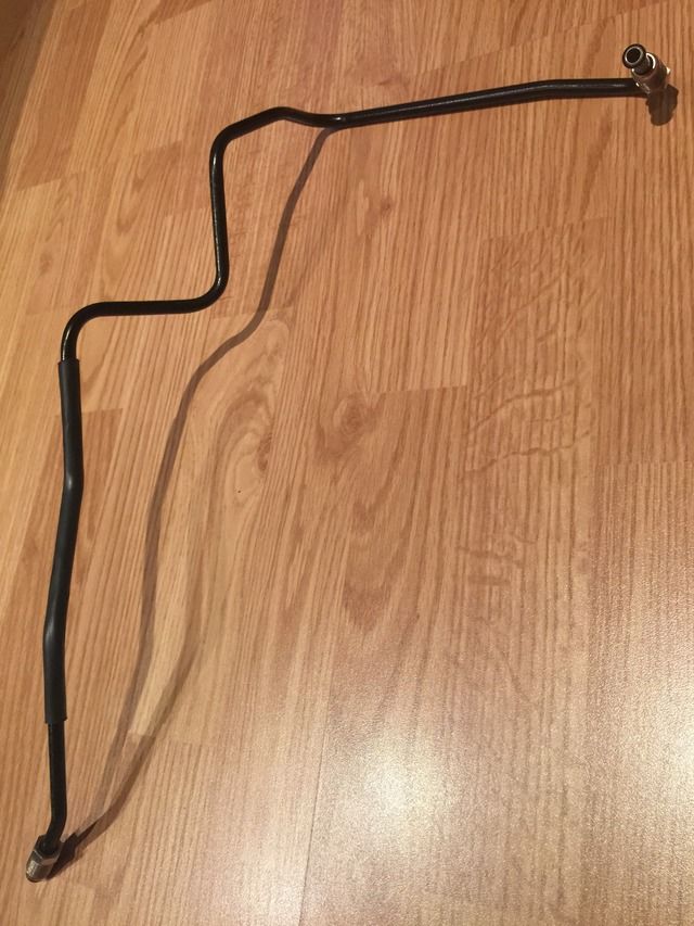 (another boring photo, but so bloody relieved am I to actually have resolved this "challenge", I just had to) I have the oil-air separator tank breather lines, swaged at one end, I just need to decide what to do at the other ends. Favourite at the moment is to keep it simple and just make up some 25mm>20mm male/male adapters. Plan B would be to make some screw-on couplings to mate onto more 90º bends the same as I'm using to fasten onto the tank. I have a couple more weld-on bosses, I can get some ally tubing, then maybe to weld one to t'other and thus maintain neat swaged pipes entirely...hmm, dunno, need to mull that one over and see what looks best vs space available. I also now have the OAS tank back from powder coating; a slight miscommunication insomuch that I masked the tank up when I was over there, decided to keep the whole V-band section uncoated...then on the drive home had second thoughts and asked to just leave the 45º chamfered edges uncoated...but the chap there, bless him, had already done it! My fault, should've thought about it a little more. 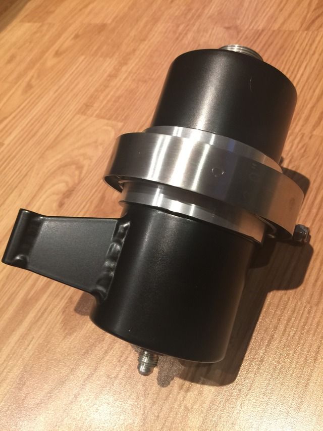 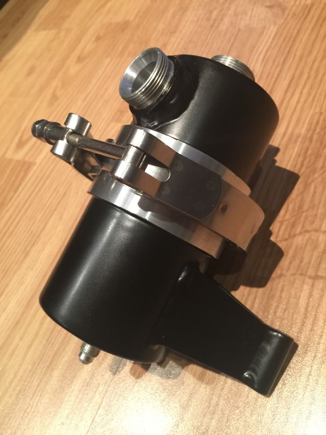 On reflection I think its perhaps best the way it is; now that the stainless clamp is fitted, I think it looks pretty smart. Also, the clamp nips up really tight to the flange faces, and I'm pretty sure that it would've made a mess of a coated surface (with it's slight additional thickness). It's all hidden in the bowels of the engine bay anyway! The lines attached.... 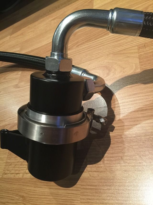  I decided to swap the 45º fitting on the drain line for another 90º fitting. This enables me to lower the mounting height of the tank without the line going uphill on its return to the engine chimney area. Next job was to modify the pillar of the IC mount again, shortening the longer section then making up a spacer to take up the spare space above the tank mounting. Trouble is, I now don't have an allen bolt long enough to pass all the way through to the helicoil in the lower pillar. Tea break over, back to work... |
||
|
07-02-2015, 01:42 PM
|
|
|
Kartoffelkopf
|
Quote:
 The shortened lower pillar, with helicoil, then an M6 stud made from a long plated caphead bolt, threaded on the plain shank, and then Loctite'd using 648 into the newly made top spacer. This spacer has 2x helicoils, one to receive the stud, the other that the IC mounting plate will then screw into. Means I can now remove the IC mounting plate on its own, without having to remove the OAS tank....easy. 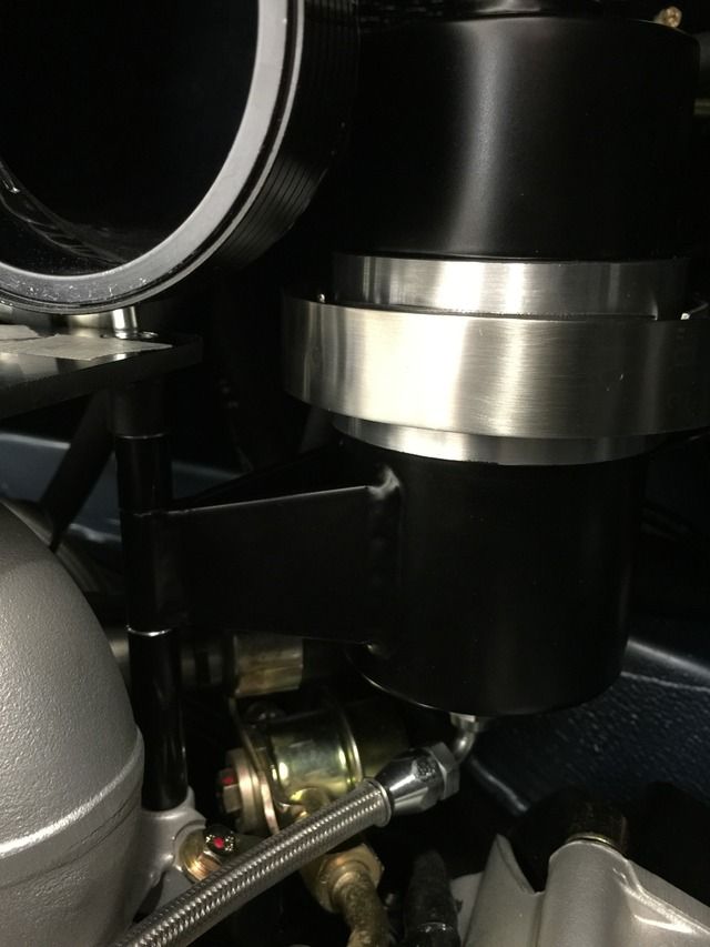 I got most of the way into installing the throttle cable last night, again, very tight access with the harness and various pipework thats right there. I got as far as re-routing it through the same aperture as the turbo oil scavenge pump return line uses (needed to loosen this to allow the throttle cable to pass...mustn't forget to refit it), the large rubber grommet needed to be carefully cut off of the cable (it wouldn't pass through the tinware), and the balljoint is now attached to the throttle assembly. Need to try and find the locking spring; no idea which bag that's stored in, but worst case I'll use some stainless lockwire. Ran out of patience while trying to contort myself to fit the rubber grommet into the bracket, so will come back to this over the weekend. Last edited by Spenny_b; 07-03-2015 at 07:52 AM.. |
||
|
07-03-2015, 07:48 AM
|
|
|
Racer

|
Are you sure that catch-can / Air-oil-separator is going to be big enough? I know my freshly rebuilt 3.9 NA motor might fill it more quickly than you might think when on track...
__________________
Preston Brown Street: 2009 911 Carrera S Coupe | 2015 Cayenne S | 1995 Audi ÜrS6 (unicorn) 1965 356 C Coupe | 2010 F250 (support vehicle) Race: 1994 964 GT2/1 | Various 944s | 2016 Superlite SLC | 2007 997 Carrera |
||
|
07-03-2015, 07:45 PM
|
|
 |
|
|
| Tags |
| 964 c4/c2/turbo , efi conversion , life racing , syvecs , turbokraft |


 1993 Porsche 911 (964) Turbo 3.3
 2006 Lotus Exige Cup 240 (#45 of 50)
 BMW M2 Competition
 BMW R1250 GS Rallye HP
 Ducati 748R


