|
|
|
|
|
| Author |
|
|
Band.
Join Date: Dec 2003
Location: Denver, CO
Posts: 13,367

|
Printed Circuit Board Question.
So, the Smonelli super-automatic espresso machine took a small dump. Indicated a "Coffee temp sensor error."
Anyway, I downloaded schematics and looked up the part. $39. No prob. Called Nuova Simonelli, and they suggested I take it to a local Italian Food Service Co. for repair. So, in good faith, I took it over. $85/hr, one hour minimum. That's fine. So, THREE WEEKS LATER, the tech, who funny enough was named "Luigi", called and said "I think I've narrowed it down to the temperature sensor." "You mean when you turn on the machine and it says "WARNING: TEMPERATURE SENSOR"? Okay, Luigi. Thanks. Anyway, I approved the installation of a new sensor, and he said he would button it up that day. ONE WEEK LATER, They call. "Uhhhhh, well, we can't get the machine to heat, we think it's the main board. New board is $632. "Sorry guys", I say. "I'll come get it." So, I get the machine home and tear into it. Unfortunately, LUIGI connected a few of the single-wire spade connectors onto the main board BACKWARDS. No electrical problem, but a problem that most likely made him replace the relay that he replaced on the board. So, if Luigi can't even keep the connectors straight, and I have a schematic, I'm going to fix it myself. If I screw the pooch, I can buy and replace the main board, which was what he was going to do anyway. I replaced the old board correctly into the machine and it heats fine, but the temp relay won't switch off. The new relay soldered into the board by Mario, er, I mean Luigi, had kind of a goober-ed up solder job, so I'm hitting the solder joints again. My question, should these big fat printed traces on the back of the board (behind the relays) have continuity with each other? i'm talking about the three main big ones. They should have continuity amongst themselves, right? I'm just trying to avoid the buying a new $6xx main board if at all possible. I'd call and scream at Luigi, but I'm not going to let his worthless ass occupy space in my brain. TIA! 
__________________
1983 SC Coupe 1963 BMW R60/2 1972 Triumph Tiger 1995 Triumph Daytona SuperIII Last edited by Gogar; 12-25-2009 at 09:56 PM.. |
||
 12-25-2009, 09:53 PM
|
|
|
Registered
|
Pretty sure real coboys don't drink espresso.
Buy a $19.95 Mr. Coffee machine and have a real cup a joe.
__________________
Pete 79 911SC RoW "Tornadoes come out of frikkin nowhere. One minute everything is all sunshine and puppies the next thing you know you've got flying cows".- Stomachmonkey |
||
|
12-25-2009, 10:03 PM
|
|
|
Registered

|
Can you post a better pic?
__________________
Make sure to check out my balls in the Pelican Parts Catalog! 917 inspired shift knobs. '84 Targa - Arena Red - AX #104 '07 Toyota Camry Hybrid - Yes, I'm that guy... '01 Toyota Corolla - Urban Camouflage - SOLD |
||
|
12-25-2009, 10:04 PM
|
|
|
Band.
Join Date: Dec 2003
Location: Denver, CO
Posts: 13,367
|
Quote:
My concern is the three big areas right here, the goobered-up solder joints were towards the bottom there. As I understand it, the points inside each of the three sections should have continuity with each other right? There's also the (not covered in resin) tracer that goes through that third, upside-down 'L" section. He kinda goobered that up, but should it matter? since all those points have continuity with each other anyway? 
__________________
1983 SC Coupe 1963 BMW R60/2 1972 Triumph Tiger 1995 Triumph Daytona SuperIII |
||
|
12-25-2009, 10:13 PM
|
|
|
Registered
Join Date: May 2002
Location: St Louis
Posts: 4,211
|
Quote:
 It does look like the solder mask was not applied to the copper in that pattern so that when it was flow soldered it would plate that area. As to why they would do that I have no idea. Want to post the link to the schematic or a picture?
__________________
Rick 88 Cab |
||
|
12-25-2009, 10:25 PM
|
|
|
Band.
Join Date: Dec 2003
Location: Denver, CO
Posts: 13,367
|
The schematic doesn't go to component level, it just shows the destinations of the molex and ribbon connectors.
 The section in question connects "FA1" to the relays, I assume it is the ground pathway for the relays. "FA2 and FA3" are the boiler heaters. When the machine gets to temp, the relays are supposed to click off. 
__________________
1983 SC Coupe 1963 BMW R60/2 1972 Triumph Tiger 1995 Triumph Daytona SuperIII Last edited by Gogar; 12-27-2009 at 12:25 AM.. |
||
|
12-25-2009, 10:33 PM
|
|

|
|
Registered
Join Date: May 2007
Location: Sapporo, Japan
Posts: 926
|
Call the company to ask :-)
ask and ask :-) they might just give you a new Mario board :-) |
||
|
12-25-2009, 10:56 PM
|
|
|
Registered
Join Date: May 2007
Location: Sapporo, Japan
Posts: 926
|
Oh!
Maybe luigi is pissed that he didn't get the smash bros game! |
||
|
12-25-2009, 10:58 PM
|
|
|
Registered
|
Jeremy, clean the resin off with q-tips and rubbing alcohol or contact cleaner. If you have solder wick, clean the joints off and carefully resolder, try not to touch each connection together.
__________________
Make sure to check out my balls in the Pelican Parts Catalog! 917 inspired shift knobs. '84 Targa - Arena Red - AX #104 '07 Toyota Camry Hybrid - Yes, I'm that guy... '01 Toyota Corolla - Urban Camouflage - SOLD |
||
|
12-25-2009, 11:04 PM
|
|
|
Registered

Join Date: Jul 2005
Location: Reno, NV
Posts: 5,941
|
Hey Jer, google the relay p/n and get a schematic of the pin out, that will help us figure this **** show out.. glad to hear it at least heats now
__________________
"Todd" 98 Tahoe ,2007 Saturn Vue 86 930 black and stock, 80 930 blue tracdog 91 Spec Miata (yeah I race a chick car) "life"ll kill ya" Warren Zevon |
||
|
12-26-2009, 08:46 AM
|
|
|
canna change law physics
|
I can't tell from the picture which solder joints are the issue. If the flat copper trace is continous, the solder can touch. If the solder runs across the board to another trace, there is the doo-doo.
Oh, and make sure the new relay isn't fried into the on position, from the connectors being hooked up wrong. I've seen things like that before, and worse... |
||
|
12-26-2009, 09:19 AM
|
|
|
What?!?!

|
If you put an ohm meter on the leads from one trace to another, you may be going through the components. Hard to tell what readings you may get. I would desolder the work he did and clean all traces using as little heat and time as possible. Re-insert components and use solder SPARINGLY! I know it's fun to say "bigger the blob..." but that just means you are not heating it correctly/sufficiently and staying on the component too long. As you know, heat is the enemy for components.
If no joy, put on the hat, call the manufacturer and use your coboy voice "Hey Darlin', muh cawfee pot done took a dirt nap me. Whut does a fella gotta do ta git a replacement board?" 
__________________
running shoes, couple tools, fishing pole 1996 Subaru Legacy Outback AWD, 5speed 2002 Subaru Impreza WRX, 5speed 2014 Tundra SR5, 4x4 1964 Land Rover SII A 109 - sold this albatross |
||
|
12-26-2009, 10:31 AM
|
|

|
|
Band.
Join Date: Dec 2003
Location: Denver, CO
Posts: 13,367
|
Quote:
The main question to me is the upside down "L" trace. There's the printed "L" trace, and then there's the solder trace down the middle of it, with no resin. All the contacts inside the trace have continuity with each other, so I don't understand what the whole "additional" solder trace thing is about. The "brand new relay" he soldered in represents the 8 points on the bottom of that picture, many near that 'solder trace', which he goobered and kind of re-connected with a new line of solder. Thanks!
__________________
1983 SC Coupe 1963 BMW R60/2 1972 Triumph Tiger 1995 Triumph Daytona SuperIII |
||
|
12-26-2009, 10:51 AM
|
|
|
Banned
Join Date: Sep 2006
Location: South of Heaven
Posts: 21,159
|
Quote:
|
||
|
12-26-2009, 11:00 AM
|
|
|
canna change law physics
|
Did he put in a new relay or temp sensor? The relay may be functioning ok, the the temp sensor is stuck on. If that doesn't help, de-solder the relay and put back on with care.
Remember, if we can't fix it, it's broke! |
||
|
12-26-2009, 11:05 AM
|
|
|
Band.
Join Date: Dec 2003
Location: Denver, CO
Posts: 13,367
|
Quote:

__________________
1983 SC Coupe 1963 BMW R60/2 1972 Triumph Tiger 1995 Triumph Daytona SuperIII |
||
|
12-26-2009, 11:06 AM
|
|
|
Platinum Member

Join Date: Jul 2001
Location: Leave the gun. Take the cannoli.
Posts: 21,218
|
Debug it one step at a time.
As I read the above, error messages are out, but the heater does not turn off? You should be able to hear or feel the relay click. If not, the relay is stuck, or not getting the signal to change. Is this correct? If it was the trace & solder, I would think it would not conduct and would not heat up in the first place. |
||
|
12-26-2009, 12:24 PM
|
|
|
Band.
Join Date: Dec 2003
Location: Denver, CO
Posts: 13,367
|
He installed a new temp sensor, which made the warning go away. I have the old one, and when I stuck it back in I got the error message again. So I'm assuming the 'temp sensor" situation is taken care of.
For some reason, he did install a new relay, which is the "coffee boiler" relay. I dont know if he decided to do this -after- or -before- he put the circuit board back in wrong. Regardless, I don't want to throw down $85/hr to have him experiment on it. I can do it for free, and I have modicum of experience with these things, so I think I can do it. So, there's a new relay, which should switch the element OFF when it gets to temp. I can hear the relay click when turning on the power, so that's where I'm at. Now I'll take the relay out completely and clean up and reinstall, hopefully with better solder joints. Thanks
__________________
1983 SC Coupe 1963 BMW R60/2 1972 Triumph Tiger 1995 Triumph Daytona SuperIII |
||
|
12-26-2009, 12:55 PM
|
|
|
Registered
|
All of the pins within a copper pad should have continuity.
You should also get continuity from one pad to the next depending on the state of the relay. There may be a diagram on top of the relay showing which pins are which. N.O. is Normally Open, N.C. is Normally Closed. You should get continuity (and coil resistance) across the relay coil. You can actuate the relay by putting voltage on the coil and test the continuity through the relay contacts. (ALTHOUGH, testing relay functionality with a multimeter is tricky as you may not have enough "minimum load" across the contacts to get a reading. Actuating the relay many times may scrub the contacts clean in this case.) You should hear/feel a click when the coil is actuated, and the relay changes state. Hope that helps! Martin
__________________
1979 911 SC Silver 2002 996 race car 2005 Ford Excursion |
||
|
12-26-2009, 12:59 PM
|
|
|
Platinum Member
Join Date: Jul 2001
Location: Leave the gun. Take the cannoli.
Posts: 21,218
|
If it is a multi-layer board, I wouldn't remove it unless you have experience with these kind of repairs.
In fact, that may be the problem, if he replaced the relay and there are traces on the component side of the board that were damaged. Follow the traces to the relay, and see if they all conduct to the corresponding relay terminals, from the other components. Try to get a schematic of the board from the manufacturer, and we'll be able to diagnose. Edit: looking back at the pics, I can see traces through the board that look like they go to the relays. See if they conduct and confirm that they should go to the relay. If they do not conduct, rather than disturb the parts, add a jumper wire. When he removed the relay, he may have disturbed the plated through holes. Last edited by dad911; 12-26-2009 at 01:24 PM.. |
||
|
12-26-2009, 01:21 PM
|
|


 1979 Porsche 911SC
 1984 Porsche Targa 3.2L
 1970/1982 Porsche 914-6/911SC 2.7 RS
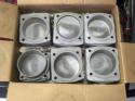 2015
2015 
