|
|
|
|
|
| Author |
|
|
Registered
|
I think you need this 5V relay module instead of the 12V.

|
||
 12-04-2016, 04:39 AM
|
|
|
Registered
|
Then you can wire the relays directly to the Arduino.

|
||
|
12-04-2016, 04:53 AM
|
|
|
Registered
|
Quote:
Quote:
Quote:
In post 76 there's a parts list. As far as I know I've been consistent when referring to the relay as SRD-12VDC-SL-C. Quote:
Schwarzy... This relay is to ON/OFF ac's compressor. I believe 12v is obligatory. After breakfast am diving back into car. Will collect as much data as possible for comprehensive status post later today. Thank you guys for your participation 
__________________
Karl ~~~ Current: '80 Silver Targa w /'85 3.2. 964 cams, SSI, Dansk 2 in 1 out muf, custom fuel feed with spin on filter Prior: '77 Copper 924. '73 Black 914. '74 White Carrera. '79 Silver, Black, Anthracite 930s. |
||||
|
12-04-2016, 05:11 AM
|
|
|
Registered

Join Date: Dec 2006
Location: Louisville, CO
Posts: 149
|
Quote:
Best of luck with your testing, Noah.
__________________
Noah 79 SC minerva blue metallic Eureka CA / Boulder CO Physics is like sex, yes there are some practical applications, but that's not why we do it. |
||
|
12-04-2016, 05:44 AM
|
|
|
Registered
|
Quote:
Continuity: Between car and relay, everything has continuity. Display is working and all readouts appear appropriate for the day. Voltage: 12v input side of new step down for 5v service to relays coil = 12v (I know now this is meaningless for this application but here it is... for the record) Output side of step down = 5v JDVCC / relays coil side = 5v via step down connection Relay has 2 Ground Pins = common ground Signal light ON, Signal Pin = 0v Signal light OFF, Signal Pin = 5v Power Pin on Signal Side = 5v 1st and 2nd relay have matching voltages. ...Sensor Failure: Yesterday, to be able to Set Temp above and below cabin temp (in order to turn system ON/OFF), cabin sensor was cooled with bag of ice. Condensate soaked sensor and it disconnected. System will not work without all sensors connected/working. Figured overnight it would dry and work today... it didn't. (System shows a sensor disconnect/failure by freezing on Porsche logo.) Replacement sensor is ordered. This does not bode well for the ambient sensor located upside down in left front fender / door jam---straight behind antenna. Question is: will ambient sensor survive driving in rain? I believe failed sensor got soaked. This soaking may be different condition than ambient sensor will ever experience. Grounding Test: Did not complete due to sending hardware to John.* On coil (left side) jumper is connected and theres common ground between left and right sides. On right, power is supplied to 5v pin. Now grounding IN2 5v to coil side: Click = ______ 12v to coil side: Click: _____ * John returned from out of town yesterday and got caught up with relay situation. While he benched the system successfully, I recall he checked the signal to the relay---which worked---but not the relay itself. No blame on him---I'd have done same. If signal is there, relay should switch (provided relay is good and wired correctly.) Bottom line John requested hardware sent to him and hell figure out what's going on. Is on the way. In the meantime, am going to look further into the sensors used for ambient & cabin data.
__________________
Karl ~~~ Current: '80 Silver Targa w /'85 3.2. 964 cams, SSI, Dansk 2 in 1 out muf, custom fuel feed with spin on filter Prior: '77 Copper 924. '73 Black 914. '74 White Carrera. '79 Silver, Black, Anthracite 930s. |
||
|
12-05-2016, 01:45 PM
|
|
|
Mighty Meatlocker Turbo
Join Date: Apr 2016
Location: North TexASS
Posts: 18,538
|
Uncle Karl, there are some seriously smart, electronics MFs posting here - am vicariously learning a lot from your thread (and having some good laughs, too, buttofcourse
 )! )!
|
||
|
12-05-2016, 02:04 PM
|
|

|
|
Registered

|
Other than cockpit sensors, anything outside the vehicle need to be weather proof (sealed).
However, if your occupants have high metabolism rates (they sweat a lot), if you ever intend to wash out the cockpit with a garden hose (like some used car dealerships do), you spill your coffee often during down shifts, the neighbor's dog sneaks inside the door you left open, you believe the climate guru's are PARF or.... if you live in an area that see's humidity for long periods of time.... 'sealed' units my friend.
__________________
Kuehl 1987 911 cab, modified https://griffiths.com/ |
||
|
12-05-2016, 03:03 PM
|
|
|
Registered
|
Quote:
)Quote:
On completely different topic... believe I heard---possibly from you---that charging AC system is best done on hothot days. Is this true? If so, what's the technical purpose/advantage?
__________________
Karl ~~~ Current: '80 Silver Targa w /'85 3.2. 964 cams, SSI, Dansk 2 in 1 out muf, custom fuel feed with spin on filter Prior: '77 Copper 924. '73 Black 914. '74 White Carrera. '79 Silver, Black, Anthracite 930s. |
||
|
12-05-2016, 03:19 PM
|
|
|
Mighty Meatlocker Turbo
Join Date: Apr 2016
Location: North TexASS
Posts: 18,538
|
Thanks for the props, Karlicous, and in celebraion of your a/c pimpin project, I present the following (since it's kind of like you are on the a/c stage!
)! Brand spankin' new material from one of my fav bands. |
||
|
12-05-2016, 03:38 PM
|
|
|
Registered
|
I'd be looking at a solid state relay (SSR) myself:
You just have to make sure that the output is DC rated. 
|
||
|
12-06-2016, 06:17 AM
|
|
|
Registered
|
Quote:
Quote:
__________________
Karl ~~~ Current: '80 Silver Targa w /'85 3.2. 964 cams, SSI, Dansk 2 in 1 out muf, custom fuel feed with spin on filter Prior: '77 Copper 924. '73 Black 914. '74 White Carrera. '79 Silver, Black, Anthracite 930s. |
||
|
12-06-2016, 05:38 PM
|
|
|
Registered
|
Just got word from John. Neither of the two relay boards are functional. Exactly why requires an autopsy (which is John's call to do or not.) Is enough for me to know they're not working. Priority is to get one that does.
Ordered 5v as backup (after learning of my interpretation error---TY guys) but before Schwarzy's input on solid state. Should arrive in day or so. That unit will go to John for his testing (before I do anything with it.)
__________________
Karl ~~~ Current: '80 Silver Targa w /'85 3.2. 964 cams, SSI, Dansk 2 in 1 out muf, custom fuel feed with spin on filter Prior: '77 Copper 924. '73 Black 914. '74 White Carrera. '79 Silver, Black, Anthracite 930s. |
||
|
12-09-2016, 08:20 AM
|
|

|
|
Registered
|
Update = John's test new 5v relay... it works with addition of 1 ground wire added to signal side of relay. I screwed up ordering replacement temp/humidity sensor---failed to place order days ago. Just discovered this fact yesterday when getting all parts together. So... will be a few days waiting on missing sensor to arrive.
__________________
Karl ~~~ Current: '80 Silver Targa w /'85 3.2. 964 cams, SSI, Dansk 2 in 1 out muf, custom fuel feed with spin on filter Prior: '77 Copper 924. '73 Black 914. '74 White Carrera. '79 Silver, Black, Anthracite 930s. |
||
|
12-23-2016, 08:47 AM
|
|
|
Registered
|
Since last post, new parts acquired include: 5v relay (replacing 12v), DHT temp & humidity sensor (replacing one I ruined during testing.) Together with new parts, John and I have been sorting through a few issue…
Refinements made: STEP DOWN & RELAY – 12v relay has been changed to5v. Dedicated power for relay has now been run from fuse panel (cig lighter fuse) to dedicated 12v > 5v step down. 5v relay has same appearance as 12v but for text printed on modules. Compared to 12v relay install, 5v relay now includes a ground added to the VCC side. (Could use single module relay here. Extra module serves as spare / back up.)  TEMP & HUMIDITY SENSORS - Two DHT temp & humidity sensors exist in system---an inside for cabin temp reporting (toArduino and data display screen), serves to compare target Set Temp to Cabin Temp with system cutting compressor OFF when both temps match. System turns compressor back ON after hystersis buffer is achieved. Outside sensor monitors ambient temp and humidity for entertainment only. Having tested DHTs under various circumstances, there’s doubt as to whether the exterior sensor will continue to operate successfully after a 100% humidity experience. Reviews say these DHTs work through 100% humidity. My experience suggests differently---but then I forced cold & humidity on the DHTs for testing purposes. Perhaps a DHT responds more favorably to “real world” temp & humidity change. Because the exterior unit is wired and Arduino is programmed specifically for the two DHTs… will leave exterior DHT to the test of time. Cabin DHT should experience no issues. With the first DHT’s failure (due my wetting it,) a new unit has replaced the wetted one. New unit was also subjected to 100% humidity. Humidity data froze at 99% (according to info displayed on the system’s data screen). Sensor was disconnected at housing terminal… humidity sensor wiped off… AC powered OFF… sensor reconnected... then system powered back ON. Sensor then resumed working properly. 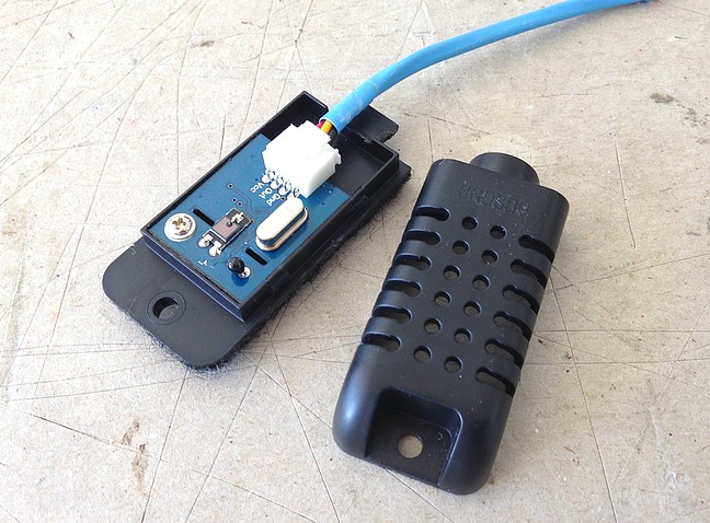 DHT sensor’s plastic housing is clamshell with friction fit. It splits in half with force applied at its seam. Wires coming with unit are terminal-attached to a circuit board that’s single-screwed into housing. 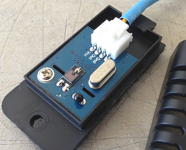 Sensor board's bottom:  DATA CABLE FAILURE – During system tests, the Set Temp control knob began working both the Set Temp and Screen Contrast adjustment. John advised there being a wiring issue. Indeed, wires at the data cable’s junction at the AC Control Box were snapping off from the junction. One is snapped here. Other wires were almost to this point.  Stress on wire connections at the junction---due to constant handling of AC Control Box---and so the cable’s repeated pivoting at the junction is to blame. My bad (for not securing cable when it was first installed.)  Old junction's been cut off and new installed (keeping all previous wire positions intact.) Cable’s now secured to AC Box with zip tie (passed through two new holes put in Box.)  Refined system was just bench-tested in car. All data collection & on-screen display is correct, screen contrast control works correctly, new 5v relay is switching compressor power feed ON/OFF correctly. John---your persistence in dealing with the info-tech / Arduino side of this journey…especially lately given my noted cable engineering shortcoming… much respect & admiration your way! REMAINING DIGITAL TEST – As mentioned above, is questionable whether or not exterior DHT temp & humidity sensor will hold up to rain of any degree. If DHT sensor fails, will see about modifying it to prevent 100% moisture from reaching sensor. NEXT STEPS - AC Control Box gets installed in center console. Console gets mounted in cabin. AC system gets evac’d & charged (brought back into operation from Black Death.) Complexity Renote Why bother complicating an ‘80 911’s AC system with digital control? This is a collaborative build-journey to explore new ideas & techniques, resolve issues that arise, and arrive at a working system as a conclusion to the creative challenge accepted at the outset... The main purpose being to gain---and share---new insights. (Complexity is a necessary byproduct here, not a goal.)
__________________
Karl ~~~ Current: '80 Silver Targa w /'85 3.2. 964 cams, SSI, Dansk 2 in 1 out muf, custom fuel feed with spin on filter Prior: '77 Copper 924. '73 Black 914. '74 White Carrera. '79 Silver, Black, Anthracite 930s. |
||
|
02-13-2017, 09:40 AM
|
|
|
Registered
|
Schwarzie... thanks for taking the time to comment/suggest 5v relay and for putting together this wiring diagram. (I'm not IT guy in this build so would be up to John to comment on your wiring plan.)
Quote:
__________________
Karl ~~~ Current: '80 Silver Targa w /'85 3.2. 964 cams, SSI, Dansk 2 in 1 out muf, custom fuel feed with spin on filter Prior: '77 Copper 924. '73 Black 914. '74 White Carrera. '79 Silver, Black, Anthracite 930s. |
||
|
02-13-2017, 01:37 PM
|
|
|
Registered
Join Date: Apr 2008
Location: Miami
Posts: 963
|
The reason we are not powering the relay from the Arduino as per Schwarz663 is due to a conversation Karl and I had, earlier in the project where he wanted to isolate the relay from the Arduino. Thus there is a separate 5V power supply to energize the relay, whereas the Arduino activates the control circuit on the relay board. In that fashion both components are separated by an optoisolator in the relay board.
As to the earlier discussions on using 12V vs 5V relays, it is irrelevant. which is used The 12 V and the 5V are the voltages necessary to energize the relay coil. The control circuit on the board used the Arduino signal in either case. The problem Karl had was that both 12V relay board were defective or damaged at some point; thus, nonfunctional. Good going Karl!
__________________
1979 SC, Slant nose wide-body cab conversion. AEM Infinity EFI, COP, supercharged! |
||
|
02-13-2017, 03:42 PM
|
|
|
Registered
|
Am back in the saddle after being pulled in various directions since last post.
Recent progress... Pin rack fault - Pin racks were added to Arduino to allow female plug-in terminal connections. Each pin can be pushed through rack if desired, also if not desired. Got system running and power began fluttering then... OFF completely. Found power pin rack being at fault. Changed rack to more solidly fixed pins. 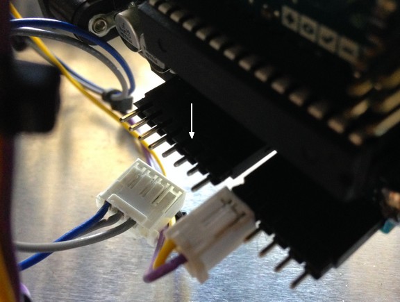 Faulty pin rack as just removed. Longer pins go into Arduino.  Bench testing system in static car. Ice is used to chill cabin sensor for testing compressor relay ON/OFF. Tilt of display in mount is intentional---is so driver sees black headliner reflected in screen.  Got system going... and relay issues persisted---albeit with relay at least switching now. Were also anomalies with data coming consistently from sensors. Minor mod to wiring and refinement of Arduino sketch/program eliminated problems. System then began operating as planned. Much respect to John for relentless participation. (BTW, John's developing Arduino-based EFI system for his supercharged engine. Will add link here later. LINK: Another AEM EFI Conversion)  Been driving with system installed in console with console attached solidly to car and AC ON for a few days. Purpose being to see if vibration & road shock will screw things up. Also to confirm consistent data collection & accuracy over various temp ranges. So far so good. Only issue found is "one wire" sensor (is in evap's core) getting lost above 98dF---it rotates between two different temps. Is no concern (since evap won't operate at that temp except to start with at times. Once below 99 there's no prob. Believe this anomaly is sensor limitation but not sure.) The highly reflective bezel does not work optimally. Depending on ambient lighting, it suffers severe reflection at times. Most of time it's good. (Toasty lately... highest cabin temp while driving, both windows open = 114dF. More typically it's in high 90s.) AC is absent refrigerant at moment. Will evac & charge next week provided digital control requires no more attention. For newcomers to thread, is relevant to recognize this project was taken on to see if and how an Arduino-based AC controller could be worked into an '80 SC.
__________________
Karl ~~~ Current: '80 Silver Targa w /'85 3.2. 964 cams, SSI, Dansk 2 in 1 out muf, custom fuel feed with spin on filter Prior: '77 Copper 924. '73 Black 914. '74 White Carrera. '79 Silver, Black, Anthracite 930s. Last edited by Discseven; 07-01-2017 at 04:04 PM.. Reason: Added link to John's ("Dr J") Arduino EFI thread |
||
|
06-30-2017, 05:12 PM
|
|
|
Registered
|
Quote:
Evap Core Temp Minimum & Hysteresis Mod: AC system's ON and OFF automated compressor control settings (32.1 dF noted above) is now thought to be too conservative. This conclusion is made prior to charging and running AC. Automated compressor ON/OFF has been changed (7.26.18) to: Minimum evap temp = 29 dFTheoretically, intent is to push slightly into evap ice-land and cut compressor OFF before ice builds too much. Hysteresis will then "bleed" off ice accumulation... allowing compressor to come ON @ 32 dF. This should provide lower vent temps than prior settings offered. Curiosity looming is how far below 32 dF can evap cope with---in Miami's humidity---before reaching an ice-block level that renders system useless? With Arduino, can reprogram evap's core temp until optimal functional temp is found. Been waiting for 90+ dF day---without rain or prior commitments---to vac & charge AC. Almost got whole enchilada a few times. More patience needed for ALL conditions to align. .
__________________
Karl ~~~ Current: '80 Silver Targa w /'85 3.2. 964 cams, SSI, Dansk 2 in 1 out muf, custom fuel feed with spin on filter Prior: '77 Copper 924. '73 Black 914. '74 White Carrera. '79 Silver, Black, Anthracite 930s. |
||
|
07-28-2018, 08:32 AM
|
|
|
Registered
|
Been waiting for 90+ dF day
Put the car in a garage with a heater. We have many shops in the west where their shops are quite warm inside. I guess their landlords won't allow them to have AC.
__________________
Kuehl 1987 911 cab, modified https://griffiths.com/ |
||
|
07-29-2018, 06:02 AM
|
|
|
Registered
|
^ Can't tell if you're in leg pulling mode or serious. IAC---Point of 90 is to charge and test ambient-to-vent temp delta all in one shot. Couple of times I've got vac going and ambient's at 90+... am thinking AC's gonna get refrig today!... then afternoon monsoon comes and ambient nose dives... then AC progress shuts down. This pattern can't go on for much longer. (August is historically the hottest month in Miami.)
__________________
Karl ~~~ Current: '80 Silver Targa w /'85 3.2. 964 cams, SSI, Dansk 2 in 1 out muf, custom fuel feed with spin on filter Prior: '77 Copper 924. '73 Black 914. '74 White Carrera. '79 Silver, Black, Anthracite 930s. |
||
|
07-29-2018, 10:49 AM
|
|


 1974 Carrera
 1979 930
 1980 SC Targa

