|
|
|
|
|
| Author |
|
|
Registered

|
Camshaft Selection -- First Draft
(This is a final version of something that I thought would be a useful technical artical for people. Thanks to Camgrinder who straightened me out on a few things and was kind enough to share his thoughts on a subject at which he makes his living. What do you guys think? - John)
How to Select a Cam Camshafts are one of the defining elements of an engine’s performance and often one of the least understood. As a result the camshaft is often selected as an afterthought which can result unintentional compromises and an engine that doesn’t perform to its full potential. In this article I will be outlining a process that can help you to select the right camshaft for your air cooled normally aspirated 911’s engine. Please keep in mind that camshaft design and the interactions between the camshaft and the engine is a very complex subject which could never be covered in a few paragraphs. My intention is to introduce the key facets so that reader can be confident that they are “in the ball park” and have a meaningful conversation with their engine builder or cam designer. At it’s simplest, the function of a camshaft is to open and close an engine’s valves in synchronicity with the pistons cycles. How it does this has a fundamental impact on the speed with which each cylinder is filled, the acoustical tuning of the exhaust and intake systems and the functional compression ratio of the engine. By the careful management of these factors it is possible to select a camshaft that will work in concert with the other components in the engine and optimize its performance. Step 1) Define the Performance Parameters Before you buy anything it is important to define a set of goals for your engine. • What is the desired rev range? For the sake of discussion it would be best to pick a 2000 RPM range where you want the engine to be strongest. The desired rev range is really a function of the intended gear box and the gap between gears. If you are running a close ratio gearbox you’ll be able to optimize the engine’s rev range for a smaller drop in rev’s after every shift. If you are running the relatively wide gearbox from a 4 speed 911T on the other hand, you might actually consider targeting a wider rev range. • Where are you going to use it? On the street? Track? Race? Are emissions important? • What sort of induction system are you planning on using? Carbs? MFI? CIS? EFI or Individual Throttle Bodies? • What sort of fuel will be used – specifically what octane? All of the factors of a cam’s design do only one thing when it comes to engine performance. That is to define the shape of the torque curve. The shape and rev range of the torque curve will by definition define the engine’s horsepower since the two are related by the following equation: Horsepower = (RPM * torque)/5252 Generally, an engine’s peak horsepower engine speed will be about 1500 to 2000 RPM above the engine’s peak torque engine speed. So the first parameter that we need to identify is where in the engine’s rev band you want the peak torque to occur. I’ve included a copy of the 2.2 liter 911S’s torque and horsepower curves below as an example.  On it you can see that see that the engine develops its peak torque of 20.3 mkp at 5200 RPM (the graph isn’t perfectly accurate). This is the “sweetspot” for the engine where the engine is pulling the strongest as a result all of the pieces being in tune and the cylinders getting the maximum charge. As the revs increase from that point the cylinder will no longer have enough time to fill completely and as a result the torque will begin to decrease. As long as the revs are increasing at a faster rate then the torque is dropping, the horsepower will increase. At 6500 RPM in the example, the torque begins to decay at a rate greater then 1 mkp (note the scale on the right) per 1000 RPM. At that point the torque is dropping off faster then the revs are increasing and so the HP begins to drop. Step 2) Cam Parameters From a manufacturing perspective there are many subtle facets of the cam’s design that need to be optimized, none of which I’m going to cover. When selecting a cam for your 911 from a number of designs, the task is somewhat simpler and you really only need to worry about 4 things. 1. Duration: In general the intake duration of the camshaft will determine where in the rev range the peak torque will occur. Unfortunately camshafts often have their duration listed based on different measurement methods. Porsche’s factory camshafts were specified based on 0.1 mm (.0039 inches) valve clearance. A reasonable rule of thumb for a 911 engine (based on the lifts being measured with 0.1 mm of valve clearance) is that the peak torque engine speed will be a function of the following equation: a. Peak torque engine speed = -3151+(Duration * 32.53) b. In the case of 911 engines, the following rule of thumb (once again based on a .1 mm valve clearance) can give you an indication of how the exhaust duration will affect a potential engine’s peak HP engine speed. While hardly exact, it can help you to understand the magnitude of the impact that exhaust duration can have. a. Peak HP Engine Speed = (exhaust duration degrees * 66.62) - 9083 2. Lift: Lift has a more subtle influence on an engine’s performance and is closely tied with the intake porting and all of the trade-offs involved in that subject. In general the greater the lift, the easier it will be for mixture to flow into the cylinders – limited by the flow in the rest of the induction system. So in general if your cam has excess lift, it won’t create any more torque and HP then a cam with the ideal lift for your engine. It will on the other hand generate higher valve accelerations (see below). If on the other hand your camshaft’s lift is insufficient for the engine’s requirements, it will limit the high RPM horsepower as the torque will drop off faster then if you had used an “ideal” camshaft. The best way to determine how much lift you should spec for your camshaft is to have your heads flowed. Below is an example of some flow data for some sampled early 911 heads.  Note that the CIS 2.4TK heads don’t flow more then 150 CFM at .4 inches of lift. In general a camshaft that provides more then .4 inches of lift will not perform much better then a camshaft with .4 inches of lift in a TK head. The 2.2 S head on the other hand (also used in the 2.7RS) keeps flowing more air all the way up to .5 inches. If you were to use an E cam which only lifts to about .4 inches with an S head, you won’t even be using the last 25 CFM of flow that the cam and heads can provide. A chart of your heads’ flows such as this is very useful for comparing the valve lifts defined by the camshaft. Ideally you want a situation where the cam has opened far enough to allow maximum flow when the pistons are undergoing their maximum acceleration. Depending on the rod-stroke ratio, this generally occurs around 75-80 degrees of crank shaft angle. Now compare the head flows with the valve lift graph for the 911 S camshaft below.  Note that the valve has opened to a point that allows maximum flow by the time that the crankshaft has reached maximum acceleration. In some cases in order to achieve this condition of full flow at maximum piston accelerations, the cam designer does have to “over-lift” the valve past the head’s peak flows just to manage the valve accelerations. 3. Overlap: Overlap can be great for extracting those last few ponies from a well tuned engine, but it’s murder if you need to pass any sort of emissions testing. The reason is that when an engine is on-cam, overlap allows a well-tuned exhaust to draw the new charge into the cylinder actually making an engine more efficient then its capacity would suggest. The downside is that when the engine is off-cam, unburned fuel can go out the exhaust causing high emissions and poor drivability and mileage. With a lot of overlap it’s also possible to have the exhaust push back into the cylinder and in extreme situations back up the intake and cause reversion. In general overlap is desirable for high RPM track and race engines, but not desirable for smooth low rev’ing street and autocross engines.
__________________
John '69 911E "It's a poor craftsman who blames their tools" -- Unknown "Any suspension -- no matter how poorly designed -- can be made to work reasonably well if you just stop it from moving." -- Colin Chapman Last edited by jluetjen; 02-05-2008 at 03:05 PM.. Reason: Changed "draft" to "final version" in the opening paragraph since I haven't needed to update this in a year or two. |
||
 09-28-2004, 11:19 AM
|
|
|
Registered
|
4. Valve acceleration: The valve accelerations designed into the cam will weigh heavily into the design of your valve train. In general Porsches factory cams had very moderate valve accelerations. As a result it is not unheard of for some of the smaller engines using the full-race 906 cam to achieve 8000 RPM reliably using stock valve springs and retainers. More modern cams have been designed to open the valves faster thus allowing the cam to act like it has a longer duration, while still keeping overlap to a reasonable level. The best of both worlds! But there are some hidden downsides. As the valves got larger and revs increase, the inertia involved with the faster accelerations goes up significantly. The result can be increased wear on the opening ramp and valve float. Valve float can be addressed by fitting stiffer springs and lightening the valve retainers. The lighter valve retainers also will help to reduce the wear on the opening ramps. In general, peak negative valve accelerations of less then .000280 inches per degree per degree can be controlled with stock valve springs. The 906 camshaft for example has peak nose acceleration of -.000261. On a more modern cam it is not uncommon to see negative accelerations of .000320 (almost 23% higher), which would necessitate the use of competition valve springs as well as potentially lighter retainers. This is especially true if you plan on spinning the engine faster then 6500 RPM.
Selecting the Appropriate Cam for Your Engine. What is the desired rev range? The lower number of your range will be close to your peak torque engine speed and will define roughly the duration that you will need. o Ball-park Intake Duration (in degrees) = (Peak Torque engine speed 3151)/32.53 o You can further refine this by looking at the top of your desired rev range. This number should be close to your peak HP engine speed. You can use the following formula to get a rough idea of how much exhaust duration you should shoot for: o Ballpark Exhaust duration (in degrees) = (Peak HP Engine Speed + 9083 )/ 66.62 Where are you going to use it? On the street? Track? Race? Are emissions important? What sort of induction system are you planning on using? Carbs? MFI? CIS? EFI or Individual Throttle Bodies? Here are some starting points o For engines that will be emissions tested, keep overlap less then 10 degrees. Also if you are using any sort of intake system that uses a common plenum such as CIS or EFI, youll want to keep the overlap to less then 10 degrees since more then that will hurt both your part throttle drivability and potentially your peak HP. o For Autocross and DE use on an engine with carbs, MFI or individual throttle bodies, target an overlap of 60 degrees or less. o For Full Race use on an engine with carbs, MFI or individual throttle bodies, youll want to target overlaps ranging from 40 degrees up to over 80 degrees. What sort of fuel will be used specifically what octane? The dicussion of fuel octane merits a whole different paper of its own. From a camshaft discussion there are a few things to consider. o Long duration camshafts can support higher compression ratios, and in many cases run better with a higher compression ratio. If you are using race fuel, you can go higher still. o On the other hand short duration camshafts with little or no overlap can create extreme static cylinder pressures in engines with high compression ratios. Steps should be taken to manage this by either adjusting the ignition timing, the cam timing, the fuel octane or some combination of these three. o If you have access to some key measurements, its possible to take these thoughts one step further by calculating your engines dynamic compression ratio. You can do this by calculating the swept volume from when the intake valve closes and adding any clearance volume in the combustion chamber, and divide this by the clearance volume. Typically the dynamic compression ratio for engines on pump fuel is 7.2:1 up to 7.5:1. For racing engines this dynamic compression ratio is generally more then 9:1. While there are still volumes more that could be learned about the black art camshaft selection and design, hopefully you will find these rules helpful in peeling back the some of the mystery of selecting a camshaft.
__________________
John '69 911E "It's a poor craftsman who blames their tools" -- Unknown "Any suspension -- no matter how poorly designed -- can be made to work reasonably well if you just stop it from moving." -- Colin Chapman Last edited by jluetjen; 06-12-2006 at 01:06 PM.. |
||
|
09-28-2004, 11:20 AM
|
|
|
Registered

Join Date: Mar 2004
Location: City of Seattle, WA
Posts: 3,374
|
Rock! No time to read right in detail right now, but very nice job, John!
__________________
Andy |
||
|
09-28-2004, 11:32 AM
|
|
|
Moderator

|
Nice!
__________________
Bill Verburg '76 Carrera 3.6RS(nee C3/hotrod), '95 993RS/CS(clone) | Pelican Home |Rennlist Wheels |Rennlist Brakes | |
||
|
09-28-2004, 02:31 PM
|
|
|
I would rather be driving

Join Date: Apr 2000
Location: Austin, TX
Posts: 9,108
|
Great read. Not to mention perfect timing, for me anyways. No pun intended.
I think there is a mistake on the first post. Calc. for peak HP at engine speed = (overlap *66.62) (+?) 9083? One of the two versions has a sign change. This version "does not compute" Could you include a description of how to find the deg. of overlap off the cam timing diagram? Is it just the area under the curve where In and Ex overlap?
__________________
Jamie - I can explain it to you. But I can not understand it for you. 71 911T SWT - Sun and Fun Mobile 72 911T project car. "Minne" - A tangy version of tangerine #projectminne classicautowerks.com - EFI conversion parts and suspension setups. IG Classicautowerks |
||
|
09-28-2004, 03:02 PM
|
|
|
Registered
|
Thanks Jamie. You spotted an problem that I hadn't, namely the peak HP engine speed formula actually should reference exhaust duration -- not overlap. I've gone back and fixed that. As far as the inconistent sign, I couldn't see it.
As far as overlap, I doubt that you could get it accurately enough off of the cam charts. I've found the best bet is to use the Exhaust closing (ATDC) + the intake opening (BTDC).
__________________
John '69 911E "It's a poor craftsman who blames their tools" -- Unknown "Any suspension -- no matter how poorly designed -- can be made to work reasonably well if you just stop it from moving." -- Colin Chapman |
||
|
09-28-2004, 03:34 PM
|
|

|
|
Navin Johnson
Join Date: Mar 2002
Location: Wantagh, NY
Posts: 8,834
|
 nice job John
__________________
Don't feed the trolls. Don't quote the trolls  http://www.southshoreperformanceny.com '69 911 GT-5 '75 914 GT-3 and others |
||
|
09-28-2004, 03:58 PM
|
|
|
Registered
Join Date: Jan 2003
Location: Langley,B.C.
Posts: 12,091
|
Holy ****e! Nicely done.
Jeff
__________________
Turn3 Autosport- Full Service and Race Prep www.turn3autosport.com 997 S 4.0, Cayman S 3.8, Cayenne Turbo, Macan Turbo, 69 911, Mini R53 JCW , RADICAL SR3 |
||
|
09-28-2004, 04:34 PM
|
|
|
I would rather be driving
Join Date: Apr 2000
Location: Austin, TX
Posts: 9,108
|
John, Here is my findings on the inconsistant sign, It has been a while since had to do algebra.
from first section. "a. Peak HP Engine Speed = (exhaust duration degrees * 66.62) - 9083" from second section. "Ballpark Exhaust duration (in degrees) = (Peak HP engine speed 9083) / 66.62." Its been while since I have done this math but. IF I use the first equation and add 9083 to both sides of the equation I end up with: Peak HP + 9083 = exhaust duration * 66.62 and finally (Peak HP + 9083 )/ 66.62 = exhaust duration which is not the equation in the second post. I am not sure which sign is correct. I can tell this thread is going to be very helpful to me and others. Its good to be able to understand what a builder or cam grinder is talking about. I think the second equation should be a minus sign. this would give 38.7 deg of overlap for the S cam graph above. This fits in your suggested range.
__________________
Jamie - I can explain it to you. But I can not understand it for you. 71 911T SWT - Sun and Fun Mobile 72 911T project car. "Minne" - A tangy version of tangerine #projectminne classicautowerks.com - EFI conversion parts and suspension setups. IG Classicautowerks |
||
|
09-28-2004, 05:37 PM
|
|
|
Registered
Join Date: Feb 2004
Location: California
Posts: 926
|
Looks good John.
The formulas for duration and peak HP numbers need another step, some way to include crank stroke. If you have an engine and change only the stroke, and keep the compression ratio etc the same the powerband will move down. Also when running a higher rod to stroke ratio the point in the intake stroke where the piston reaches maximum velocity is later than a lower rod to stroke ratio. (connecting rod length / crankshaft stroke = Rod to stroke ratio) The "overlap cycle", or "5th cycle" as Ed Iskenderian terms it is very hard to define. Because you have both ports exposed to the cylinder and the piston moving into the combustion chamber and then away it is very dificult to know what is really happening. The port sizes, combustion chamber shapes, piston dome shape, valve lift during this cycle all have a dramatic effect. A high dome racing piston might block some of the effects of the overlap cycle, while a low dome style piston can give the intake charge a straight shot out the exhaust pipe. My number one parameter when choosing camshafts is the intake valve closing point. This is the ultimate governor for RPM. Later closing = higher RPM, early closing = low rpm. The optimum scenario is to set static compression based on intake valve closing to achieve the desired dynamic compression ratio. Next is exhaust valve opening. If the exhaust valve is not open enough by bottom dead center the piston will have to push the exhaust gasses out creating a pumping loss. Early opening = high rpm, later opening = lower rpm. Notice on your S camshaft valve lift curve, the exhaust valve is open +/- .150". Not very far. Since the pressure in the cylinder is extremely high right after combustion the exhaust flows out, but at high rpm the torque can fall off because of a pumping loss.
__________________
John Dougherty Dougherty Racing Cams |
||
|
09-28-2004, 11:01 PM
|
|
|
Registered

Join Date: Sep 2000
Location: Bournemouth, England
Posts: 1,099
|
Excellent, information.
Thanks Alan.UK
__________________
-------------------- Always learning |
||
|
09-29-2004, 12:31 AM
|
|
|
Registered
|
Camgrinder;
You pointed out that... Quote:
To accurately predict what you are describing, you would need two engines, one with a larger bore and a shorter stroke, and the other with a smaller bore and a longer stroke, but both engines of the same capacity. Using the same camshaft and induction systems, valve size, etc., I maintain that in general you will get the same performance from both engines. Surprisingly, there are relatively few occasions where this has occurred. One obvious case in the 911 world is the 2.5 liter ST engines which were built both with 66 mm cranks and 70.4 mm cranks (and corresponding changes in bore to maintain a 2.5 liter capacity). Near as I can tell they both had essentially the same peak torque engine speeds and peak HP engine speeds. I have yet been able to find anyone who can provide dyno charts or published torque and HP numbers of a similar back-to-back test that supports that long stroke = more torque and lower rev range conclusions. Disclaimers: I'm assuming reasonably normal piston speeds here, if the piston speeds are very high for the short stroke, engine, then the long stroke engine will perform differently. I've also heard that engines with a higher rod-stroke ratio tend to work better on induction constrained engines since the piston "lingers" at TDC longer allowing the exhaust inertia to draw in more intake charge during overlap prior to vacuum caused by the piston's intake stroke sucking this charge back into the cylinder. I'd be interested in seeing someone post a comparison of piston travel to rod length, but that's a subject for another thread. Points not being argued... John, I agree with your 2nd and 3rd paragraphs. The points that you are making tend to be more precise then I was presenting. I was just trying to distill the subject down -- which necessitates consolidating some details. Your point about intake valve closing point is essentially included in my intake duration formula since the intake valve's opening point is largerly defined by TDC and the amount of overlap desired. The same applies to the exhaust valve opening which is included in my (corrected) peak HP equation, except in that case it is the closing point that is defined by TDC and overlap. I'm not disagreeing that there isn't more subtlity to the subject, just that this piece was intended as primer, not a thesis. Besides it's not my intention to give away all of the cam grinder's secrets. Just raise the level of the overall conversation.
__________________
John '69 911E "It's a poor craftsman who blames their tools" -- Unknown "Any suspension -- no matter how poorly designed -- can be made to work reasonably well if you just stop it from moving." -- Colin Chapman Last edited by jluetjen; 09-29-2004 at 08:53 AM.. |
||
|
09-29-2004, 08:29 AM
|
|

|
|
Registered
|
Jamie;
Great eyes!!!  Quote:
  The correct equation as you point out should be... Exhaust Duration = (Peak HP + 9083 )/ 66.62 So let it be written. So let it be done! 
__________________
John '69 911E "It's a poor craftsman who blames their tools" -- Unknown "Any suspension -- no matter how poorly designed -- can be made to work reasonably well if you just stop it from moving." -- Colin Chapman |
||
|
09-29-2004, 08:45 AM
|
|
|
I would rather be driving
Join Date: Apr 2000
Location: Austin, TX
Posts: 9,108
|
Good to know I wasn't seeing things.
I just realized that I made a mistake in trying to predict the sign. I was thinking in terms of overlap, not exhaust valve duration. Its like a lightbulb went off in my head. Oh, I am always still learning, and learning, and...
__________________
Jamie - I can explain it to you. But I can not understand it for you. 71 911T SWT - Sun and Fun Mobile 72 911T project car. "Minne" - A tangy version of tangerine #projectminne classicautowerks.com - EFI conversion parts and suspension setups. IG Classicautowerks |
||
|
09-29-2004, 09:26 AM
|
|
|
Registered
Join Date: Feb 2004
Location: California
Posts: 926
|
O.K . I will refine my statement to read:
If you have an engine and change only the stroke, and keep the compression ratio, intake sytem and the displacment the same the powerband will move down. My belief on the long rod is, A higher the rod to stroke ratio will delay the point of maximum piston velocity during the intake stroke. Giving the cylinder a little more time to fill.
__________________
John Dougherty Dougherty Racing Cams |
||
|
09-29-2004, 04:18 PM
|
|
|
Registered
|
You asked for it....!
Ok; here's my updated and corrected attempt to quantify the affects of rod length and stroke within a 911 engine. Please -- I'd welcome anyone and everyone to doublecheck my method and math and point out any goofs so that I can fix them.
Conclusions 1) This graph is pretty straight forward.  2) On all of the engines the peak piston speeds occur between 78 and 80 degrees ATDC. The 66 mm stroke engine reaches it's peak piston speeds at about 80 degrees ATDC, compared with the other longer stroke (and shorter rod) engines reaching their peak speeds closer to 78 degrees ATDC. So Camgrinder is right, a longer rod will result in the peak piston speeds being reached later allowing more time for the mixture to flow in. But in the case of the 911 engine, the difference between the longest rod version and the shortest rod version is no greater then 2 degrees. For Reference, here are the rod/stroke ratios for the different configurations: 66 mm stroke: 1.97 R/S ratio 70.4 mm stroke: 1.82 74.4 mm stroke: 1.69 76.4 mm stroke: 1.63 Now let's keep Camgrinders premise that everything else is kept the same (bore, valve size etc, but as a result not the capacity which will have by definition grown). From a cam design perspective, it would appear that by that by the time piston reaches it's peak speed point in the cycle, the longer the longer stroke (and smaller rod/stroke ratio engines) engines would have travelled further and thus have reduced the cylinder pressures at that point more then the short stroke engine. This is because the mixture is being drawin in through the same sized valves and ports. Look at the distance travelled graph above. I wonder if this would increase the "pumping losses" in the engine? Look at the example of the 911ST motor below. This be another reason why if you add a stroker crank to a motor and change nothing else, (increasing the capacity and reducing the rod/stroke ratio) that cam acts "mellowed" since short rod/stroke ratio motors demand more flow earlier in the process.  3) The longer stroked engines have faster accelerations as expected, but all of the engines have the same acceleration rate at about 68 degrees ATDC. 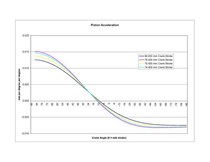
__________________
John '69 911E "It's a poor craftsman who blames their tools" -- Unknown "Any suspension -- no matter how poorly designed -- can be made to work reasonably well if you just stop it from moving." -- Colin Chapman Last edited by jluetjen; 10-02-2004 at 07:34 AM.. |
||
|
09-30-2004, 02:23 PM
|
|
|
Registered
|
OK, this may be wondering far afield from the original premise of this thread, but the point was brought up about the relationship between stroke and camshaft selection.
Off-line Camgrinder mentioned the following to me: Quote:
My competing theory: The increase in leverage is largely offset by the smaller force being applied to the piston as a result of it's smaller diameter (keep in mind that we're talking cubic capacity is fixed) and increased displacement. So some of the pressure is used just moving the piston the extra distance. Since the combustion pressures will be roughly the same, if the stroke is 10% larger, thus causing a 5% increase in the torque on the crank (since the crank only grew by half of the stroke increase), it will be offset by the 10% reduction in piston area. The net result is no gain if you ignore such things as changes in the engine's internal friction and stuff like that. For example, Porsche's 911ST motors: 
__________________
John '69 911E "It's a poor craftsman who blames their tools" -- Unknown "Any suspension -- no matter how poorly designed -- can be made to work reasonably well if you just stop it from moving." -- Colin Chapman |
||
|
10-01-2004, 08:08 AM
|
|
|
Registered
|
It's amazing how much trig you can forget in 37 years!!!! I've replaced my earlier graphs (comparing 66 and 70.4 mm stroke geometry) with new graphs (Listing all 4 stroke lengths) based on corrected trig calculations. Let's just say that my earlier attempts were just wrong, I won't list all of the errors.
Go back up and reread the stroke post and let me know.
__________________
John '69 911E "It's a poor craftsman who blames their tools" -- Unknown "Any suspension -- no matter how poorly designed -- can be made to work reasonably well if you just stop it from moving." -- Colin Chapman Last edited by jluetjen; 10-02-2004 at 07:35 AM.. |
||
|
10-02-2004, 06:49 AM
|
|
|
Registered
Join Date: Feb 2004
Location: California
Posts: 926
|
It would be interesting to see a 76.4 stroke engine with a r/s ratio of 1.97 on the graph.
__________________
John Dougherty Dougherty Racing Cams |
||
|
10-02-2004, 08:39 AM
|
|
|
Registered
|
Here you go...
   It looks like the peak piston speeds have about a 2 degree difference with the shorter rod version hitting it's peak piston speed at 78 degrees and the longer rod version at 80 degrees. This can be seen best on the acceleration graph (also known as the derivitive of the speed graph) where the two lines cross 0. When they cross 0 is when the pistons have 0 acceleration (peak speed) and start to deaccelerate. Camgrinder, how do you think that this would impact the choice of cam or a cam's design?
__________________
John '69 911E "It's a poor craftsman who blames their tools" -- Unknown "Any suspension -- no matter how poorly designed -- can be made to work reasonably well if you just stop it from moving." -- Colin Chapman Last edited by jluetjen; 10-02-2004 at 09:48 AM.. |
||
|
10-02-2004, 09:10 AM
|
|


 1969 Porsche 911E 2.0 E
 1976 Porsche Carrera 3.0
 1995 Porsche 993 Carrera Coupe

