|
|
|
|
|
| Author |
|
|
Kartoffelkopf

|
Cheers Chris

|
||
 10-23-2014, 06:54 PM
|
|
|
Kartoffelkopf
|
Evening folks,
A light week in terms of activity on this car....This last few weeks I've had to become the instant expert on 997's to help my Brother buy his very first Porsche! Long story short, he collected it on Friday, a beautiful Arctic Gen1 Carrera S, with all the bells-and-whistles. Needless to say, he's happy as a sand-boy and thoroughly deservedly, self-employed and works his arse off. 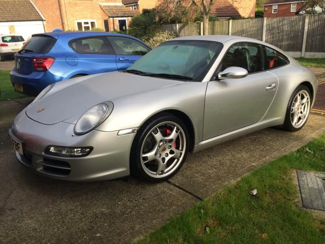 It's also had all the remedial work done to fix the perennial bore-scoring issue with the later M96's and M97's (a very extensive engine rebuild, heads refurb, chains, liners, pistons, ramps/guides), plus preventative installation of a new IMS bearing (his has the final larger type, thankfully). All this work performed by Hartech in the UK, at great expense to the dealer who commissioned the work; Hartech are an extremely well thought of outfit, a bunch of true engineers that go to daft lengths to show their working, explain their thinking and testing....anyone that hangs around on PistonHeads and (I think) 911uk will have read Baz Hartechs extremely detailed commentary. So, we're now bullet-proof, and this example absolutely goes like stink, consensus being from those that have driven numerous 997 Carrera's/S's that this feels far punchier than most, belying it's book number of 351hp. Compared to my old 996.2 GT3, I have to say it's a more usable power delivery, feeling far stronger in the midrange but of course not that wild last thousand rpm or so that the Mezger is famed for. Damned-sight more usable on the public highway though. Progress, eh? Also a shout out for Peter Morgan, who a lot of folk would have heard of via the Porsche periodicals and perhaps his inspection company...oh and his long hood resto project on YouTube in association with Nick Fulljames @Redtek. He did a stellar job with Ollies car, I've never seen such a thorough and well presented PPI report. Money extremely well spent. So anyway, back onto the air-cooled stuff again..... Fuel lines are now in place. Pumps were re-worked to remove the outlet spacers, thus aiding clearance for the front pump in the recess, and the rear one versus the power steering pump reservoir....thanks for the heads-up on that one Chris Looks a lot neater, and less joints to potentially leak.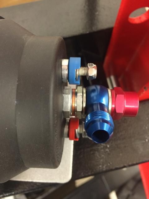 I also took a look at the banjo fitting on the feed to the front pump. Chris did suggest using the new tank>pump hose un-cut along with a straight push-on screw-in coupling that he sells...and that would've been great, had I not already cut the new hose down a lot shorter, to then feed the pump with a very straight path. --->  Of course, had I known that after carefully trimming it back shorter and shorter I'd only end up with a short stub of hose, I could've saved £20 and just used some spare fuel hose I have kicking around! Doh! Never mind. What I did do, upon Chris's thoughts that it may not flow as well as the straight fitting, was to look at how the banjo and retaining through bolt alignment. Per the pics below, if you get the bolt positioned such that one of the 3 feed holes is aligned with the neck of the banjo, you do get a decent sized aperture, in addition to the circumference "ring" of the banjo on the outside of the bolt. I marked up the 3 hole positions on the hex of the bolt head, then positioned the banjo neck such that once tightened, it all lined up. Hoping this will be ok, if not then I'll order another new hose plus Chris' fitting. Correctly aligned ---> 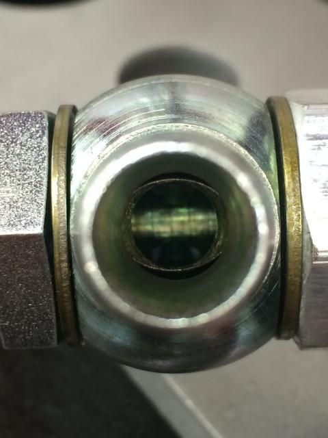 Incorrectly aligned ---> 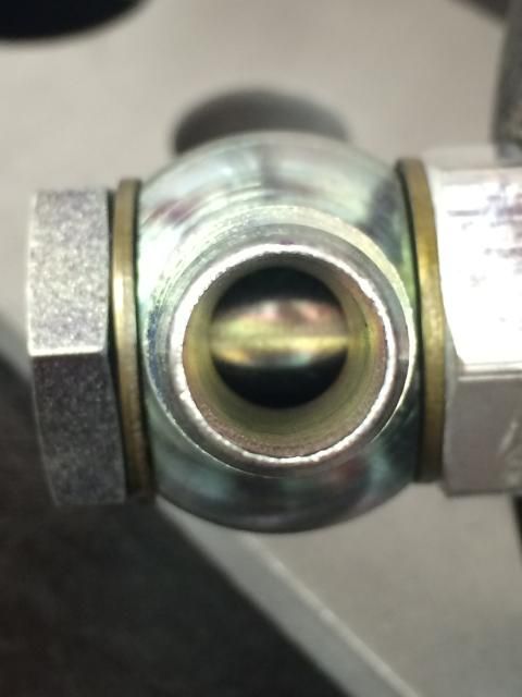 Marking the bolt ---> 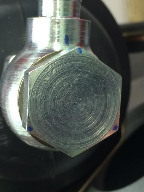 As I'm keeping the carbon canister in the LHS rear arch, I need to also keep the small hose that vents back into the tank. The original fittings for the rigid lines have been reworked slightly to now accommodate the 2 x -6AN hoses but also to keep the vent line in place. Waiting for some electrical ring terminals to arrive, so I can fit them onto the power feeds for both pumps (the +ve feeds are now M6 binding posts on the 044's) I've also now removed the Zeitronix wideband monitoring system I installed only a few months before taking the car off the road. Fitting the Lambda sensor for the Zeitronix, plus the sensor that the ECU needs would've compromised the gas reading to one or the other, so I kept it simple with the ECU being the critical benefactor of accurate Lambda readings. Also, there's really no need for it as I'll be data logging with the MBE, and can now use the OBDII port on the ECU loom to interface with an iOS device via an ELM327 bluetooth ODB dongle. I was thinking about installing the Zeitronix system into the Lotus; may still do it when the spring comes and I fancy tearing stuff to pieces to install, but need to think about where it'd mount in the Exige cabin so that it's useful / visible....on the other hand, it may just go on eBay....as good as new, not a mark on it. The weather here in the south of the UK was great today, meaning the car could be rolled out to continue the old engine management harness and control unit removal. Some careful thought needed in reading the wiring schematics, to ensure I'm not going to create problems with other systems in the car when I remove the harness for the 3 control units under the passenger seat.  Was amazed to find out that the 2 small control units (Accelerator Control Unit and Turbo Control Unit) are now almost $800 each, assuming you can actually get one!!! Needless to say that they're now carefully stored somewhere safe. The next activity was to examine the original dealer fitted immobiliser system but for obvious reasons, I'm deliberately not going to go into any detail on this on a public forum. Need to carefully remove part of the brand new carpet set I also installed when I first got the car....hindsight would've been handy....the few areas I've tried look to be coming up without too much effort and without damage, but they do need to be removed so I can remove that old management harness that runs through to the engine bay, down the LHS side of the engine. More tomorrow.....hopefully... |
||
|
11-01-2014, 06:21 PM
|
|
|
Kartoffelkopf
|
Minor update this evening; got diverted onto pet rescuing duties when I got a call from my daughter saying that her guinea pigs had got out and found their way under the decking in the back garden....perfect timing, it's been throwing it down all day - and as-of 10pm, we still haven't retrieved them yet. Cue one very tearful 8yr old!
But, a quiet few hours in the Skunkworks this evening has finished off the fuel lines, now all trimmed to length, fitted with couplings, routed, clipped into place and finally tightened onto the pumps and filter. Rear pump ---> 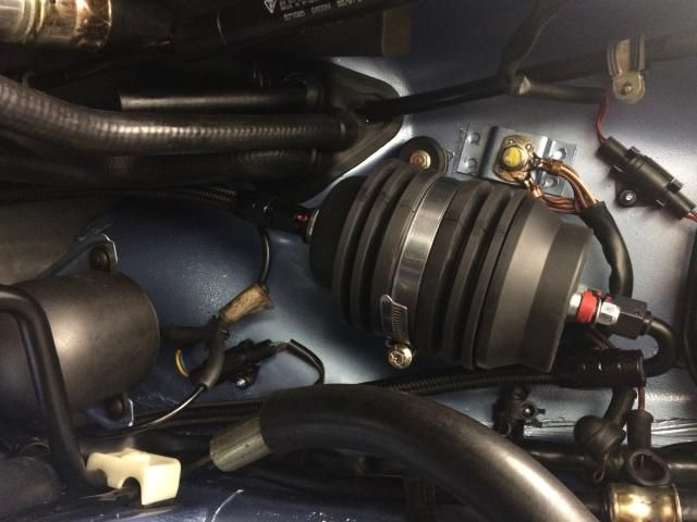 Which then links across to the input to the filter, carefully routed up against the sound deadening in that channel previously used to run the solid fuel lines for the CIS ---> 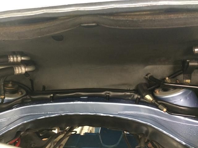 ....and then to the input of the filter. Below the filter, dangling, is the 45deg coupling for the fuel rail return line back down to the tank (the line that runs from the output of the filter to the fuel rail is on the engine) ---> 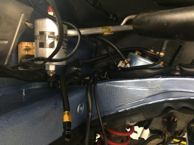 Nice to actually finish a job for once! Seems like I've got lots of partially finished minor projects on the go at the moment. Next job is to get some engine stuff done....loom clipped into place, sensor bracket fixed back on once I receive those electrical ring terminals to connect the dashboard boost sensor. |
||
|
11-02-2014, 05:33 PM
|
|
|
Moderator

Join Date: Dec 2001
Posts: 9,569
|
Great Progress! Your attention to detail is incredible.
How long till you put a Turbo on Ollie's car?
__________________
'66 911 #304065 Irischgruen 96 993 Carrera 2 Polarsilber '81 R65 Ex-'71 911 PCA C-Stock Club Racer #806 (Sold 5/15/13) Ex-'88 Carrera (Sold 3/29/02) Ex-'91 Carrera 2 Cabriolet (Sold 8/20/04) Ex-'89 944 Turbo S (Sold 8/21/20) |
||
|
11-02-2014, 05:43 PM
|
|
|
Kartoffelkopf
|
Quote:
Quote:
It's quick enough as stock, them German ponies are tres-schnell! ...besides, I don't want to be blown into the weeds by a kettle driver, do I?! Last edited by Spenny_b; 11-03-2014 at 04:28 PM.. |
||
|
11-02-2014, 05:50 PM
|
|
|
Kartoffelkopf
|
A few more hours playing in the garage this evening; can't get onto doing the engine stuff as the electrical parts haven't yet arrived but I did remember that I haven't yet finished off the LHS front wheel arch....opportunity to finish another item and get it off the To-Do list.
Only simple stuff, but quite satisfying to empty another couple of lin-bins of fixings. A bit worrying when you can't quite account for everything (!) but the good old PET helps to decode what goes where (I really must get better at photographing EVERYTHING when I take stuff apart. Too much enthusiasm when dismantling. The A/C condensor wasn't finally fastened into place, and did notice that it was fouling the washer tank, preventing it from being bolted into place.....became obvious why, the inner rubber post that pushes up into a locating bracket on the tub, wasn't seated into the hole. A quick unbolt and re-assembly and everything is much better, the seals are tight against the chassis and the pipes that run to it are now out of the way from the washer tank. Easy.  (you can just about see it above the ballast resistor) A/C receiver/drier is now fixed back onto the freshly plated mounting bracket. The p-clip and the large 2-piece pipe clamps are also now in place...which was bloody tight to get it fitted over the rubber separators. 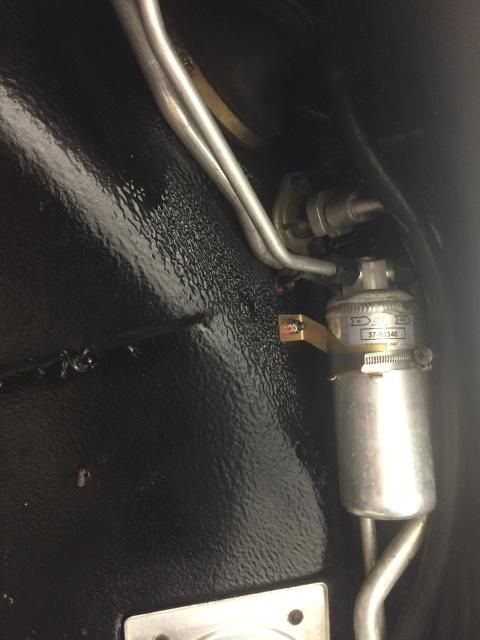 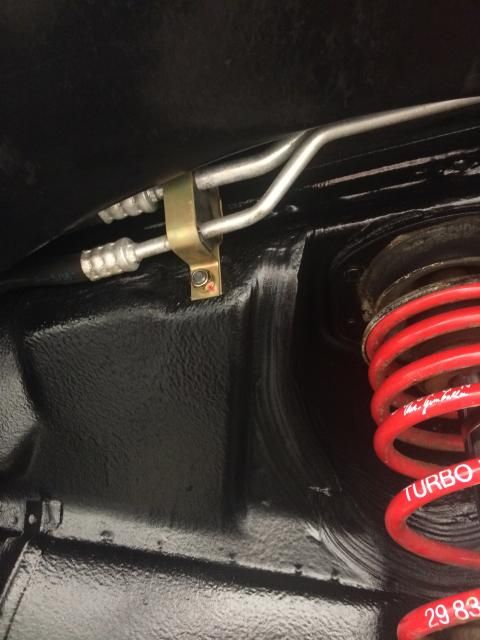 Minor stuff, not that interesting (sorry), but it's another step closer. ************************************************** *********************************** Now...I need a little help please (I may also post this question in the 964 forum) In removing the wheel arch stuff a while ago, I drained off the washer tank, and despite being careful, the drain plug must've gone brittle and sheared straight off when unwinding it....trouble is, Porsche don't list this drain plug as a spare part, only the whole tank assembly.  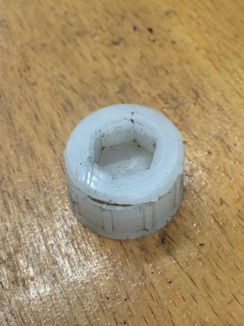  Anyone know where to get one? Or what thread it may be? Or a part number from another model...924/944/968/928 that may use this part, that I can order? Have tried supergluing it but it just separated straight away. Thanks in advance guys.... ETA - Just been having another look in the 964 PET, and lo-and-behold, there's a part number for Item #33 in section 904-10 described simply as a "plug" p/n 964 628 194 00....but there's no Item #33 shown in the diagram, hence why I didn't see it! Good old Porsche.... ETA again - Ignore the above, the part numbers *really are* just plastic plugs, not the screw cap....dammit Last edited by Spenny_b; 11-13-2014 at 03:06 PM.. |
||
|
11-03-2014, 04:27 PM
|
|

|
|
Registered

Join Date: Mar 2005
Location: Phoenix, AZ
Posts: 2,862
|
Funny to see you work on a water pumper. The more we work on them, the more we appreciate you hear the air-cooled !
|
||
|
11-03-2014, 05:54 PM
|
|
|
Kartoffelkopf
|
Quote:
Just getting back into Ollies car to manoeuvre it up and down the driveway felt like putting on a familiar pair of shoes (...use whatever analogy you like); everything was familiar with the couple of 996's I've had. They are lovely things, and a shed-load of car and performance for the money, really out of kilter versus how much you could easily spend on a new well spec'd very-average-daily-Euro-box-snotter. When it was parked next to the Exige over the weekend, it did get me thinking; they cost (give or take) the same sort of money, the 997 is about a year newer, but the fit and finish of the 997 was just in another league. When I got into the Exige for a quick blast, all was well again, its an experience like very few others can deliver......but it did get me thinking. |
||
|
11-04-2014, 12:21 AM
|
|
|
Registered
|
Quote:
I hope it is ok to chime in with some OT? I went back to the shop today, they help me do some tig welding. Took a few pics: It is not Porsche, but I believe it might be from the same year as my 930 Pure art.  And the engine.  Ferrari T3 These guys do old school attention to detail. It is a pleasure to see the attention you put into your work as well.
__________________
Jesper Carrera 3.0 1975 930 1978 OEM Matte Schwartz, ANDIAL IC, BL WUR, SC cams. LMA-3 w. XD-16 and CP transducer www.stauningwhisky.dk |
||
|
11-07-2014, 09:59 PM
|
|
|
Kartoffelkopf
|
Quote:
You're too kind, Sir. ...the trouble is, the more I do, the more obsessive I get! It'll never get done at this rate, it's like one giant engine-based, living fractal!That's fantastic engine pr0n, that crank, lovely piece of engineering. Thanks for sharing. Love looking around places like that. Last edited by Spenny_b; 11-29-2014 at 10:51 AM.. |
||
|
11-29-2014, 10:49 AM
|
|
|
Kartoffelkopf
|
Well, it's time for another update - been a while. Not much happened a few weeks ago for various reasons, long-and-not-particularly-interesting.
Aaaaaanyway....Have now got a few tasks underway, and another weekend to myself to get a few of them completed. I remembered I had some dollies I bought years ago, so quickly retrieved them, bought a couple of sheets of decent SWG steel (to prevent the castors digging into the pit boards) from Pete the Welder, and now I'm able to shift the car right over to the other side of the garage....full door open access to either side (no, UK garages are generally nowhere near as big as your US "warehouse" sized garages!) 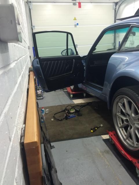 I've now removed the passenger side interior so I can extricate the old wiring harness to the Jetronic management and the other gubbins. Some care needed to gently remove the stuck down carpet set, then a case of delving into the (extremely sticky) sound deadening material. 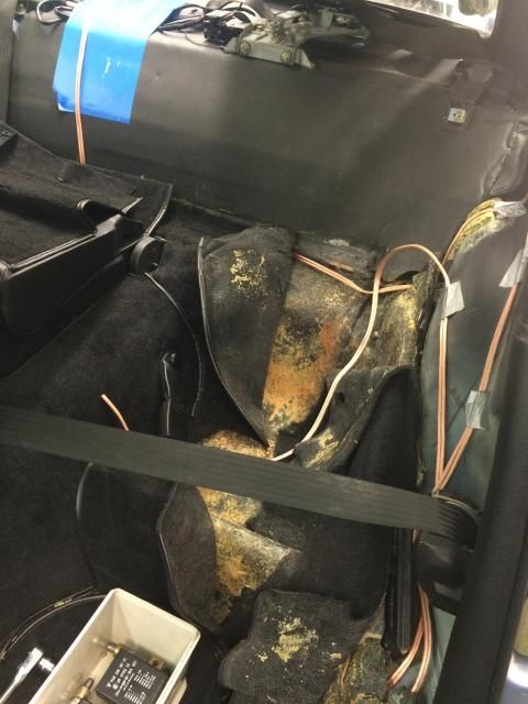 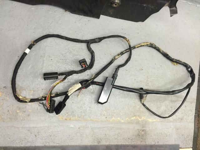 Rather than try and reuse (butcher) the original mounting plate for the control systems under the seat, it's easier and neater to make a new one.....some 1.6mm ally is just right, and I can just about squeeze the MBE and AEM thermocouple unit onto it, along with the 2 x harness plugs for the electric seat and fuel pump / ECU control. Very happy how it's come out, and have decided to add some nutserts into the chassis to enable quick(er) removal. Pics to follow tomorrow.... The original plan was to run the new harness up under the centre console, then through the access hole near the handbrake, then along the underside of the transmission tunnel to the engine bay. From here, the 2 x MIL spec connectors would interface with the engine loom through the rear tinware, very close to the turbo oil scavenge pump. But...until I get the engine into the car for an accurate assessment, the measurements were just appearing too tight, i.e., the outer connectors (from the cabin) look like they'll be extremely close to the damper turret box section that runs across the back of the bay (or at least, the part under the rubber sealing skirt, near the damper/spring) So, Plan B. Seeing as the whole section of loom that runs from the engine to the underside of the passenger seat is no long needed, I've re-used that hole, grommet and space in the sound deadening to run the new loom, meaning it now enters the engine bay on the top half not the underside. With a particularly nice brew of tea in my hand, I had the brainwave of being able to mount a right-angled section of ally to a spare 15mm high mounting face on the back of the Carrera intake, right behind the LHS intercooler mount. 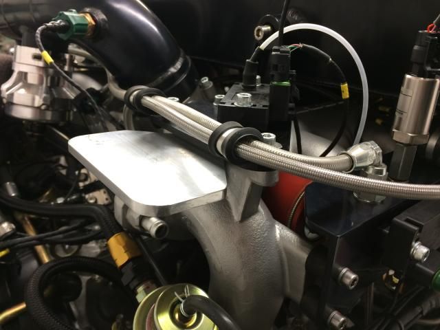 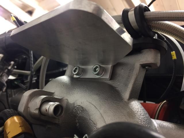 Keeps it all in the clean part of the engine bay, and is more accessible. In fact, very accessible with the IC removed. 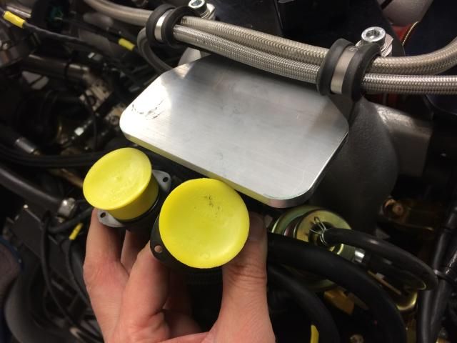 Have been making the bracket today, it should be finished tomorrow with the holes needed for the MIL connectors and fixing screws. It'll go for anodising next week. The front pu is now back on....hurrah, some space recovered in my home office! A previous owner fitted some RS-alike brake ducts instead of the OE driving lamps, but there purely for cosmetic reasons, as there's only a 2p sized hole behind them. 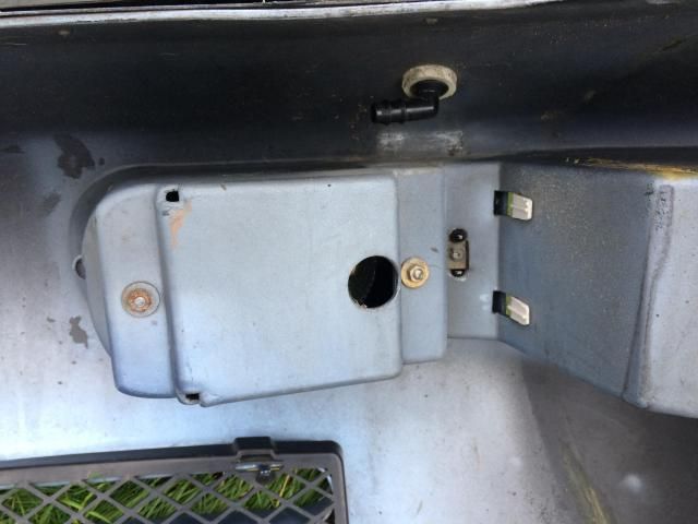 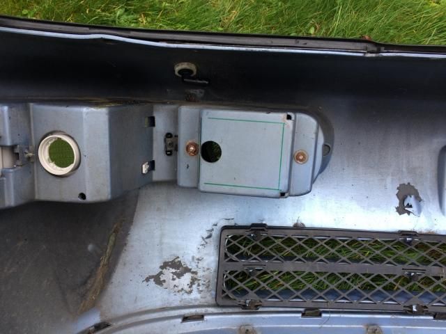 No use to man nor beast. So, some quick sabre saw action to remove that whole rear section, and the ducts will now flow a tonne of cool air to the AC condenser and the oil cooler radiator. Just a few of the underside screws to fit along with new spring clips. Another job to get done this w/e is to fabricate a mounting plate for the ignition amplifiers. Four of them, and they ought really to mount onto a nice solid lump of ally, which'll act as a nice heat sink (they come with a mounting paste, similar to CPU/heatsink paste, if you've ever built your own PC). The plan is to mount them where the old EZ69 ignition module used to go, at one end of the engine fuse and relay carrier plate....need to relinquish a cereal packet from it's daily duties to mock something up. 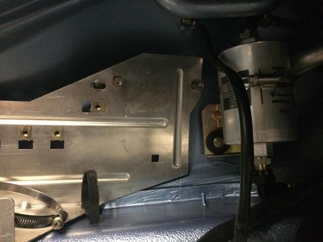 The engine harness is now finally on the engine, with a few little mods to make some of the runs neater. Have punched in a few holes on the tinware, needed for the harness to reach the lower bank of coils. Tinware will go for a quick re-coat this week as well. Front fuel pump assembly is now finished and back in it's cubby hole; bit of a wrestle to get all the pipes aligned with clips not fouling and the wiring routed neatly...but worth spending the disproportionate amount of time (!)....I suppose. :roll eyes: Needed to rework the fuel return line, as the -6AN fitting sat exactly at the narrowest part between the pump cover and chassis. So, make the hose shorter so the -6 is in the cubby hole; thankfully there was enough slack in the hose run to shuffle forwards. More updates tomorrow.... Last edited by Spenny_b; 11-29-2014 at 05:53 PM.. |
||
|
11-29-2014, 05:48 PM
|
|
|
Registered
|
Hello Spencer !
I look forward to hearing your car to hum. 
|
||
|
11-30-2014, 10:31 AM
|
|
|
Kartoffelkopf
|
Post weekend update time…..
Well, a great weekends work! Tackling this project one Post-It note at a time, seems to be more productive than the ubiquitous whiteboard full of tasks. So, some detail of the harness bracket. On paper, it could be a very simple bent piece of aluminium….but of course, that will never do for me, it needs to be way over the top to be worthy of fitting to this engine. So, starting with a battleship grade piece of extruded right-angle section from Pete the Welder (he’s becoming my metal stockest as much as go-to welder). It's nominally 6mm and far to big in stock form, a good exercise in “how light can I get it” whilst still retaining the strength I’m looking for. The area on the intake that this is mounting on is actually fairly limited, perhaps only 45-50mm wide (it looks wider, but there’s a “kick” in that mounting face,meaning it’s not quite flat along its length) and 15mm tall, hence over-spec’ing the thickness of the extrusion, I knew there wouldn’t be much material on the mounting face. Some trimming to get the excess corners removed, then time to measure the positions of the MIL Deutsch connectors. Now, the tricky thing with these, is that because they’re ultra-dense and light as hell, they’re also very compact with very little wiggle-room for mounting. The main hole cutout tolerance is very tight, as the mounting holes run very close to it. Masking tape, a compass and some accurate chain drilling was how I initially set about doing it, but after trying to get one of the holes perfectly round without a taper (and not getting very far), it dawned on me that the perfectly good 4-jaw chuck for the lathe was sitting there doing nothing…..ah-hah!.... 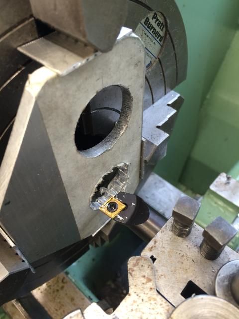 Mounted so that the roughed-out holes were concentric to the centre-line and we’re good to go. Carefully. Very very carefully. As you can imagine, a roughed-out chain drilled hole has the potential to rip the piece from the jaws if too big a cut is taken. One of the jaws was also protruding so far out that it only cleared the bed by fractions, perhaps 1mm….terrifying. A couple of hundred rpm and gently-does-it. Flip it over for the other hole, and a slight complication; my whittling away of excess material on the mounting face had left me unable to tighten one of the jaws; thin-air doesn’t hold too well. A quick bit of guerilla engineering to drill and tap an off-cut, and we’re good to go again. 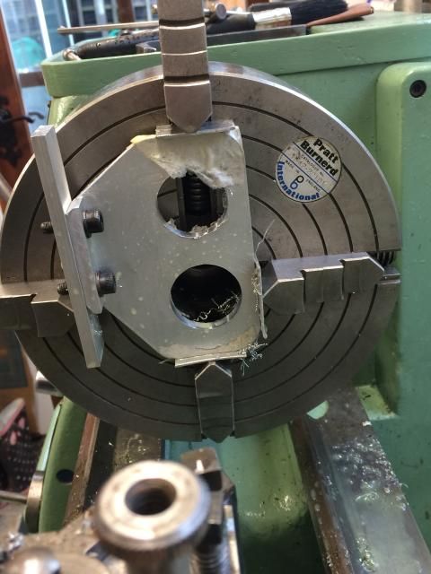 Finish off with a nice, decent-speed pass for a light finishing cut, and we’re bang on dimension and square….far better than a day spent filing (and justification for me buying that 4-jaw; something I’ve not had the need to use since I was an apprentice, way-back-when)  Next opportunity for some machining work – the material thickness is too great for the connectors; the connector specs state a max of 3mm, and this measures up as 6.27mm. Hopping onto the pillar-drill-come-mill for some more careful light cuts to recess the mounting face area. Took a good hour of pretty light cuts, but the X-Y table yet again proved it’s worth and made the job a cinch. Got it down to 2.5mm just to be sure, don’t want to have to re-work after it’s been anodized. Finally, time to be super-accurate and get the flange mounting holes drilled. Also time to grow a 3rd hand to hold the bracket, position the harness so the cables exit exactly where I want them, and then mark it. Got there after a few attempts and found some nice countersunk allen set screws, will look super neat and avoid any fouling against the other half of each connector…trouble is, the countersinking takes it really close to the connector hole (see what I meant earlier?). 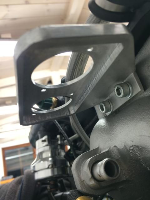  Finally, time to build it up and see how it looks. Very pleased indeed. So many opportunities to screw-up a weekends work at each stage, but got it spot-on without so much as a fettle to the mounting holes; left shoulder’s now sore from me self-congratulating myself. Pics below are just a quick build-up, connectors not tightened-up, hence the small gap under the fixing plate. 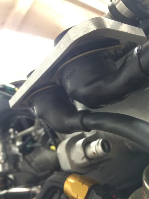 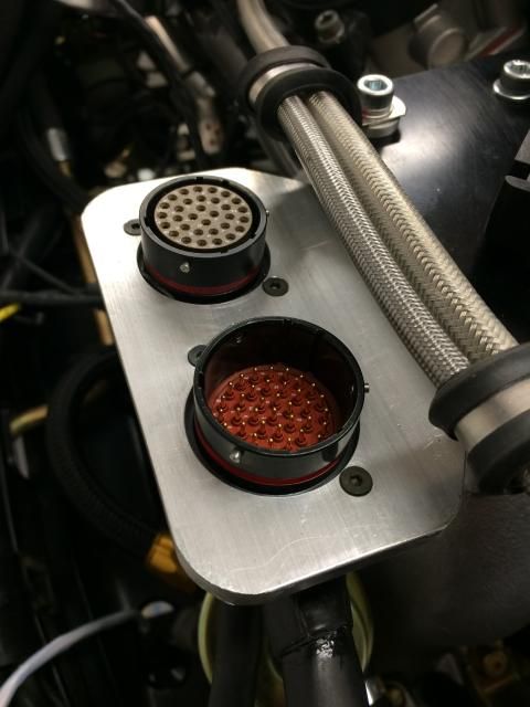
Last edited by Spenny_b; 12-02-2014 at 01:55 AM.. |
||
|
12-02-2014, 01:53 AM
|
|
|
Kartoffelkopf
|
So, whilst on a roll, time to have a go at the exhaust backpressure sensor mounting. The sensor for Cyl 1-3 is on the left hand bracket that holds all the other sensors, but there was no candidate for doing similar on the right hand side for 4-5-6. There are, however, a couple of unused 7mm holes on the side of the A/C and power steering pump brackets:
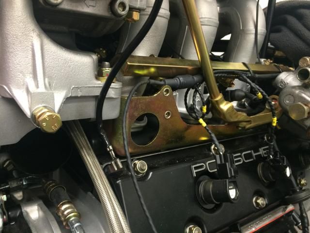 A couple of options; commit the piece to re-plating (again) by welding on an M5 or M6 nut on the back. Or tap the hole (the diameter's just about ok for an M8 thread), but that means having to use M8 fasteners that are way too heavy for such a small bracket. Decided to use Nutserts, the lightweight option (!); as luck would have it, the 7mm hole is spot-on for an M5 Nutsert, so plating can remain intact. Using the same right-angle extrusion proved ideal…although I did go a little too tight dimensionally once all the rough edges had been machined square. All ok though, everything clears well, and the sensor is nice and tight to the engine rather than dangling in free-air. 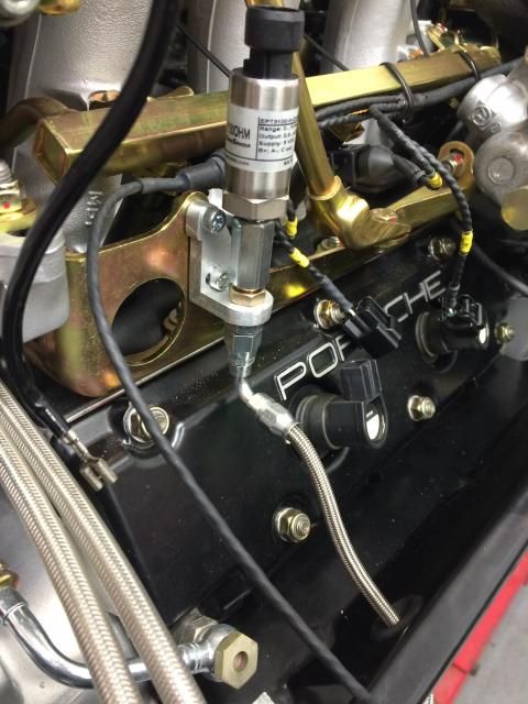 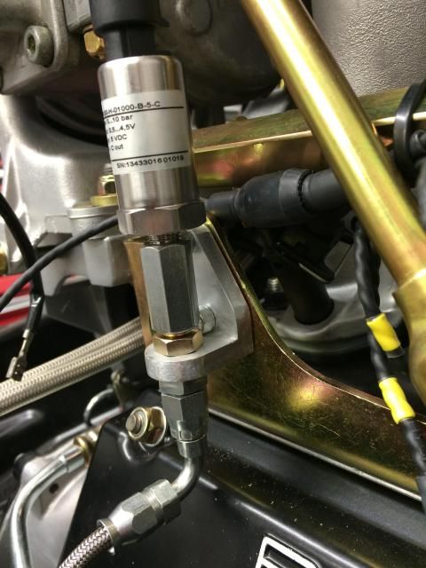 Holes now punched into the tinware to allow the braided EGBP hose to pass through, plus another for one of the wastegate pipes (somehow I’d not allowed for one of these hoses – or rather, if I did, then I can’t remember how I intended it to pass to through to the underside of the engine bay), and finally the one for the lower bank of CoP's that I mentioned previously.  There's one more hole to punch in the opposite piece of tinware (on 1-2-3), to allow the cam position sensor harness to pass, then they can both be re-powder-coated. Next job is to make the ignition amplifier mounting, then the blooming eThrottle assembly that I keep putting-off. Once they're made, it’s time for a final polish of the new parts, then off to the plating shop. A week or so should then give me an opportunity to re-install the interior, get the passenger seat out of my conservatory and do some other finishing jobs. Sorry, that’s a couple of very long post to just update you on two brackets, but hey, I’m chuffed with them, and it’s actually left me with not-that-much to finish on the engine before it goes back in the car. In fact, the only thing I can think of is to fabricate the inlet pipe to the turbo, but the engine needs to be installed so I can see how the air filter will sit. Last edited by Spenny_b; 12-02-2014 at 02:08 AM.. |
||
|
12-02-2014, 02:05 AM
|
|
|
Moderator
Join Date: Dec 2001
Posts: 9,569
|
Chuffed indeed! British Aerospace is alive and well...in your garage!
__________________
'66 911 #304065 Irischgruen 96 993 Carrera 2 Polarsilber '81 R65 Ex-'71 911 PCA C-Stock Club Racer #806 (Sold 5/15/13) Ex-'88 Carrera (Sold 3/29/02) Ex-'91 Carrera 2 Cabriolet (Sold 8/20/04) Ex-'89 944 Turbo S (Sold 8/21/20) |
||
|
12-02-2014, 04:07 AM
|
|
|
Kartoffelkopf
|
Quote:
 (I never worked for BAe, before you think I 'alf-inched 'em) (I never worked for BAe, before you think I 'alf-inched 'em)
Last edited by Spenny_b; 12-02-2014 at 04:48 AM.. |
||
|
12-02-2014, 04:22 AM
|
|
|
Kartoffelkopf
|
Evening folks....post-weekend update time.
Lots done this last week in the evenings, and a pretty productive weekend...lets test my memory to see if I can remember it all.... The mounting plates for the ignition amplifiers are both finished. Surprising how long it takes to make them, bearing in mind they look like very basic pieces of plate, but it's a case of making sure that the harness feeds won't foul anything, then trimming a couple of the edges to ensure that with vibration, they won't touch the adjacent fuel filter, then making the stand-off mounts, with an adjustment to bring the top plate in tighter.  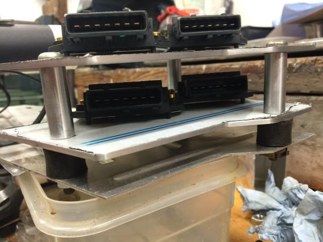 (the height of the top plate is now reduced, but this shows the principle of how they'll mount) 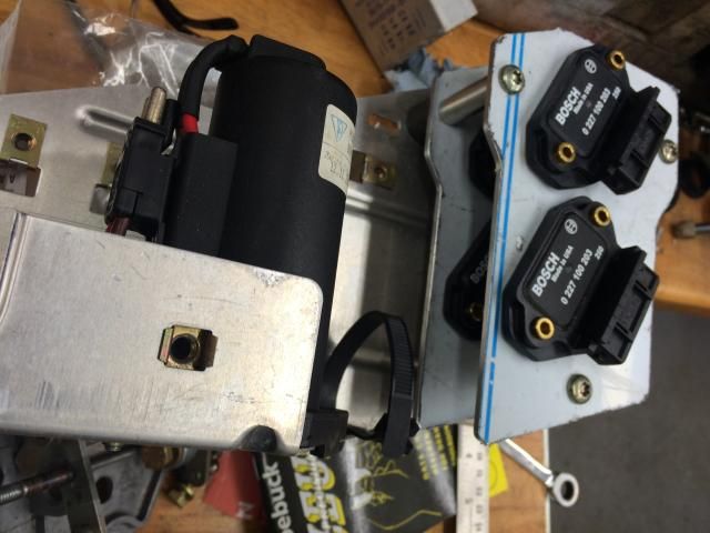 With these plates, it's a rare case of more metal=better (without going too OTT), so that they can act as heat sinks. All these pics are early shots, and they've since been tweaked and radiused to make them a little neater. The amps mount very neatly with some M4's, and the harness should run exactly where it needs to, to avoid the stand-offs, filter, etc. The plates were then given a brushed polish ready for anodising. Black, of course. 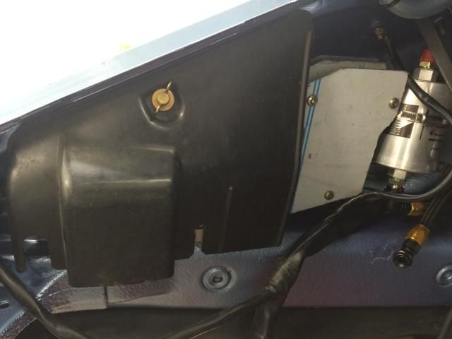 A new pillar for the RHS intercooler mounting was a quick job I've been meaning to do for ages. Despite all efforts to make sure nothing moved whilst welding the IC outlet > throttle body pipe work (i.e., tacking it in-situ whilst bolted up), I guess with the natural movement that ally does go through when welding ha's meant that the IC needed to be moved about 1.5mm higher to align the two halves of the trick clamp. The throttle linkage is FINALLY finished...although not for want of some head-scratching. When I went to bolt on the bracket that holds the cable grommet and acts as a guide, I suddenly realised that there was nowhere to bolt the rear fixing; the new design just didn't allow for it. So, a quick rethink and it'll now use a different front mount, plus a new mounting that I got Pete the welder to buzz on, on Friday. 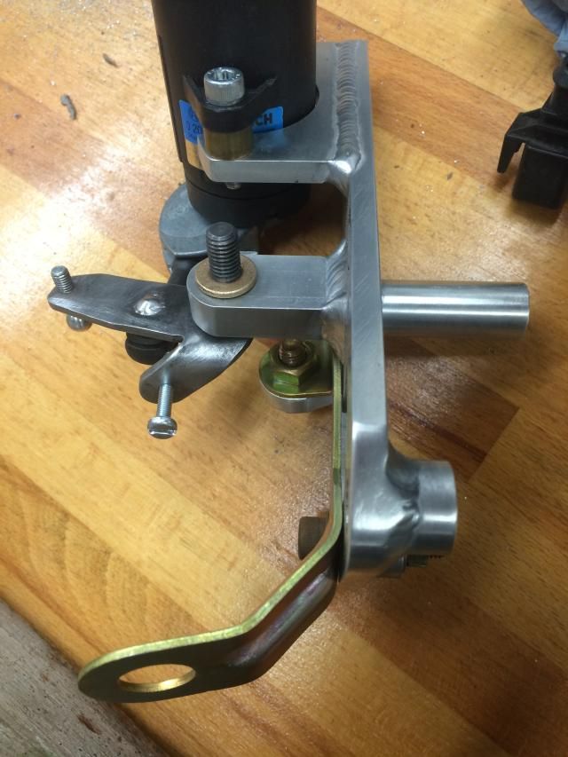 The linkage assembly was also remade; the first attempt from a few months ago had the ball joint (that the throttle cable actuates) sitting too close to the pivot, thus only 50mm of cable travel was possible when the eGas was fully rotated. It needed to be 58mm, so version 2.0 now has this mounted higher, plus a neat throttle stop return that will use an M4 screw and locknut to prevent the eGas pot from being over rotated (although interestingly, if pulled hard enough, there is a provision for over rotation after overcoming a detent...ok, so that was that interesting...). On-and-off, I've been tinkering with this blooming throttle assembly for well over a year, possibly 18mths - so glad it's now done. I hope. So re-routing of the throttle cable will be needed so that it enters that support bracket in its new position, but that should be straightforward, possibly some tinware adjustment. 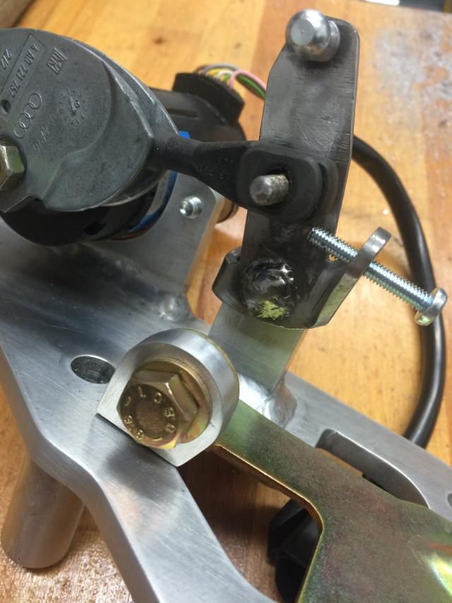 This is all pre-welding, but you can see the new additional support with the M8 bolt holding it ready for buzzing. The plate used to mount the ECU and AEM thermocouple control units has now been finished. I needed to add 2 x cutouts to accept the connectors for the seats and the 6w T15 connector which we're using to control the fuel pump relays and to switch on/off the ECU itself. Also required were a few holes to fit the cable tidying clips/ties. 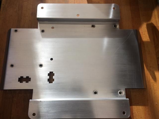 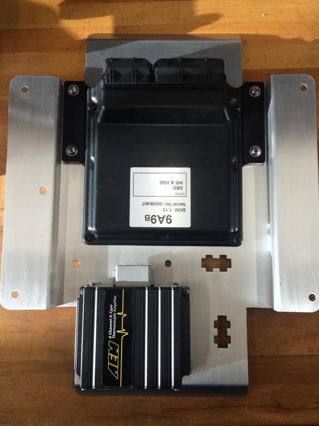 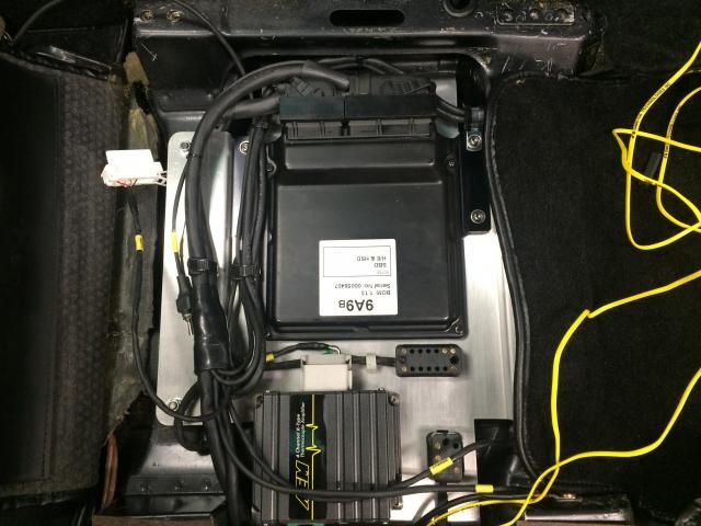 Lots of harness to route and keep neat, but I'm pretty chuffed how this has come out. Everything runs nicely, but not quite able to finish the interior install just yet; the 2 x K-Type thermocouple extensions I bought with the sensors aren't long enough @ 8ft each. They're going to run alongside the new harness, through the rear bulkhead grommet and into the top side of the engine compartment, so a 10m reel of higher grade wire has just been ordered; increased temp rating (+400degC) with overbraiding so that it won't spoil the aesthetics! The engine bay relay and fuse board is now back in place, harness clipped into place and ready for the ignition amps to be fixed to it. Another task I finally got around to yesterday, was repairing the relay for the rear window heater - the large silver cased unit in the pic below. Stupidly, ages ago when the car was spending quite a lot of time being rolled in and out of the garage (when the workshop/garage was being remodelled) rain water got into the relay, as the harness was unclipped from the chassis and dangling down. When I moved it, sure enough, it all drained out. Dammit. I opened it up for an inspection, and fingers crossed, it looks to be ok apart from one electrolytic capacitor that fell off; A 10mile trip and 47pence later, the new one's in place - but I have to confess to not yet testing it. It could still be a £50 mistake.... 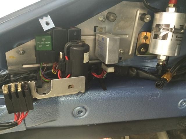 Powdercoated gearbox cover brackets now bolted back on; these are the supports for the plastic under tray, covering the transmission. There's now only 2 more items left in the powder coating box! The RHS tinware on the engine is also now back from being re-re-powdercoated. Per the previous update, some additional holes needed punching into the tin, so it's been done properly to ensure it won't succumb to corrosion and is now back on the engine. A delivery over to the plating shop was made the other day - I always seem to do it, and time my urgent batch of work perfectly with the Christmas break! Lots of stuff that I need doing so that I can finish the engine, and John's certainly going to try and turn it around before the 23rd, but it's by no means a certainty. But hey, gradually getting there, just lots of small jobs to get sorted; as with any job that involves getting stuff neat, it takes daft amounts of time but is well worth it. Last edited by Spenny_b; 12-15-2014 at 01:40 AM.. |
||
|
12-14-2014, 04:24 PM
|
|
|
Kartoffelkopf
|
Another quick update - tonnes of stuff done this evening.
The new loom that runs inside the cabin has now been partially hidden; the section that runs up the side of the transmission tunnel (2 x breakouts for wheel speed sensors, plus the main +Ve feed that is coming from the starter motor) are now buried in a channel I cut into the sound deadening, so that it doesn't sit proud under the carpet. These pass through the huge grommet that's behind the handbrake, under the storage bin in the centre console. Once through to the trans tunnel, the +Ve feed and the wheel speed sensor connections are cable tied to the rigid handbrake cable tube....not quite figured out how to fix the harness that runs to the front sensors. 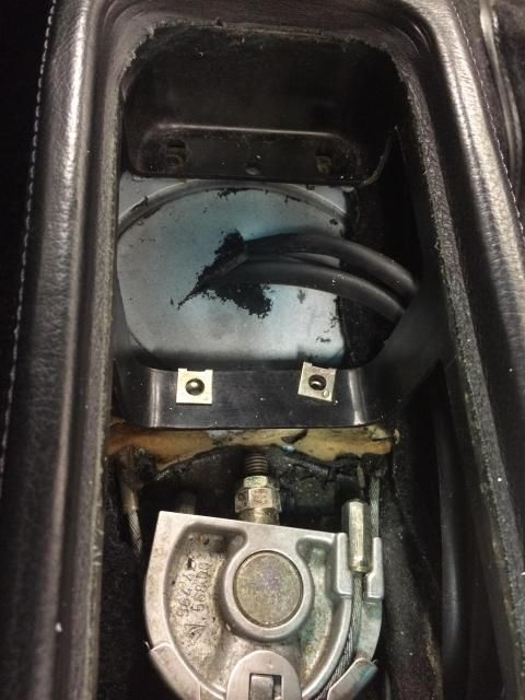 Thermocouple wire should arrive tomorrow, then will be able to finish the harness run through to the rear bulkhead, and get the rear trim back together. Both EGT sensors are now installed - a little tricky with fingertip only access, and the braided sensor wire thats fighting you, but in and ready for connecting. Engine loom is now cable-tied permanently in place. Oil feeds to the turbo and to the oil pressure sender are both now tightened (there's clearly a reason why I didn't tighten them both last year - I'm sure I'll remember exactly why in a few days...) ...And a job I've been meaning to do for ages, that will hold-up the engine reinstallation if I don't get it done, is to get the rear wheel speed sensor timing wheels made. I guess they can be made later once everything's in, but some of the bracket fabrication will be a right pain - lot easier to do it now. We're using a couple of toothed wheels to provide the signal to the HE sensors; they don't need to have the same resolution as a crank position wheel, in fact we only need about 8 teeth. The plan is to sandwich these between the gearbox output stubs and the driveshafts, then fabricate some mounts to hold the hall effect sensors in place. 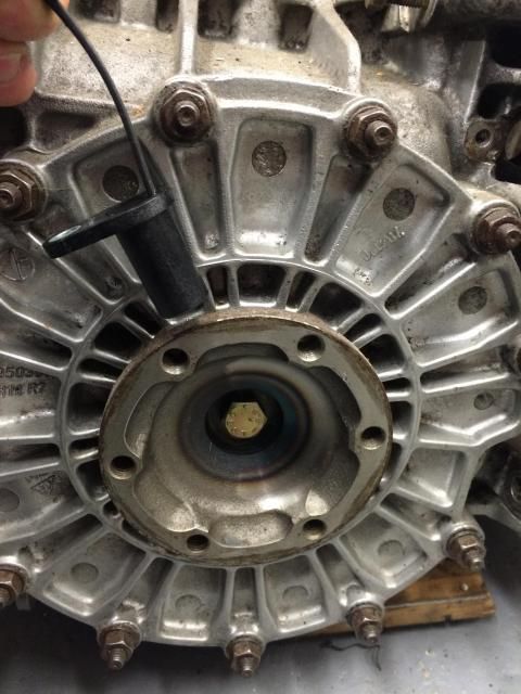 One bracket will mount off of the diff cover studs; the other side (starter motor side) isn't quite so straightforward, but I'll figure that out tomorrow. So, what I needed to know are the dimensions of the output flanges (inside and outside diameters plus mounting PCD), and how much lateral sprung movement in the driveshafts, which will determine how thick the timing wheels can be. 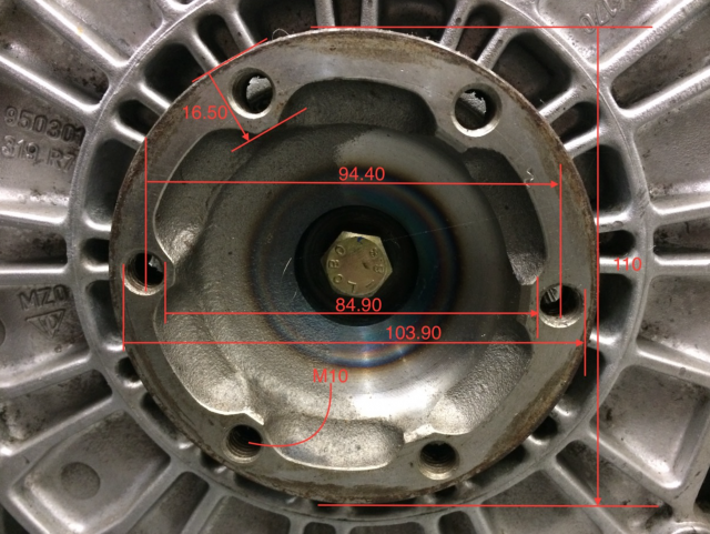 Time to dig out the quad-bike ATV lift and get the gearbox in position under the car. Always amazes me how damn heavy that gearbox is. 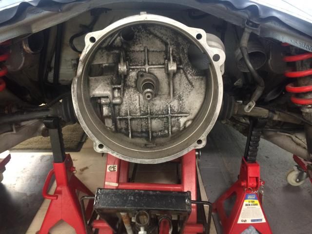 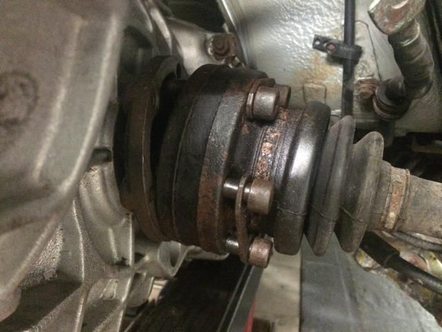 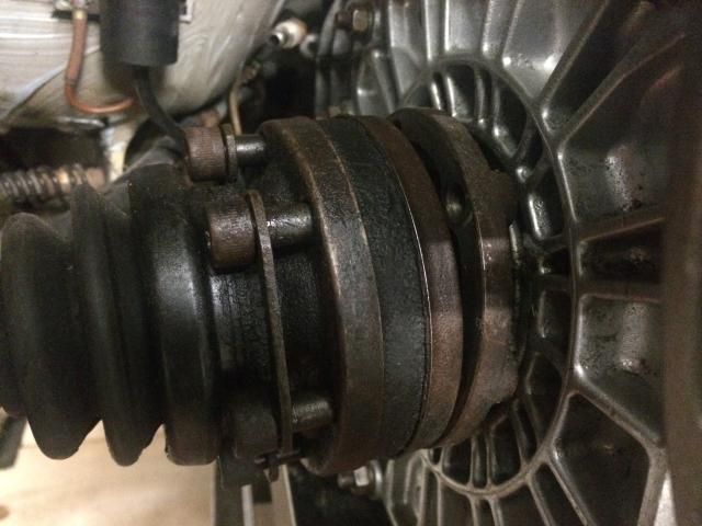 As it turns out, there's loads of play; an average of 22mm per side, so using material that's 3-4mm thick should be no problem. Craig @ SBD is going to look after getting these water jet cut, I'll then get them plated in a few weeks after Xmas. Last edited by Spenny_b; 12-15-2014 at 05:32 PM.. |
||
|
12-15-2014, 05:27 PM
|
|
|
Kartoffelkopf
|
I dont know whether theyve put something in the water recently, but it seems to be full of Vitamin get-stuff-done. Seriously excited by the amount of jobs now getting finished. Those jobs that once seemed to be an age away in terms of even thinking about getting done, are now either sorted, or the next on the list to do.
Let me try and remember what Ive got done since the last update (I did have it all typed in an update, until Yosemite decided to have yet another black-screen-of-death, and rebooted itself. Terrific) The interior is now all back in place:
So its all back together apart from the centre console, which Ive deliberately kept loose until I decide where Im going to mount the 2 x rotary switches for the adjustable boost and traction control. At the moment, one of the favourite options is to re-use the storage bin underneath where the 3 x switches are located in the centre console. Remove the bin and make a mounting plate, probably recessed to prevent accidental movement of the switches. Another option is to perhaps use the ashtray in the lower knee roll. I removed the ashtray itself ages ago but kept the leather front trim, then made a rotating mechanism to accommodate the Zeitronix Wideband Monitor. When not required, it neatly rotated 90 upwards, held with a magnet and just looked bone-stock with the leather trim. I may try and reproduce this, but I know that the space under the shelf may not be enough to allow the switches/harness to tuck up into; it may have to be permanently on show, which starts looking a bit aftermarket (IMHO). The K-Type thermocouple wire did arrive the other day; not quite what I was expecting, as its a single core type not multi-core. Not ideal, but should be ok, as its not a high duty application with regards to constant movement and risk of fracturing. On the plus side, its really really small in diameter, so easily hidden with the new harness that goes from the ECU to the engine bay. Ill just need to think about how Im going to mount the (disgustingly ugly, but only option with ease of connectivity) connectors, then cut the wires to length and terminate. 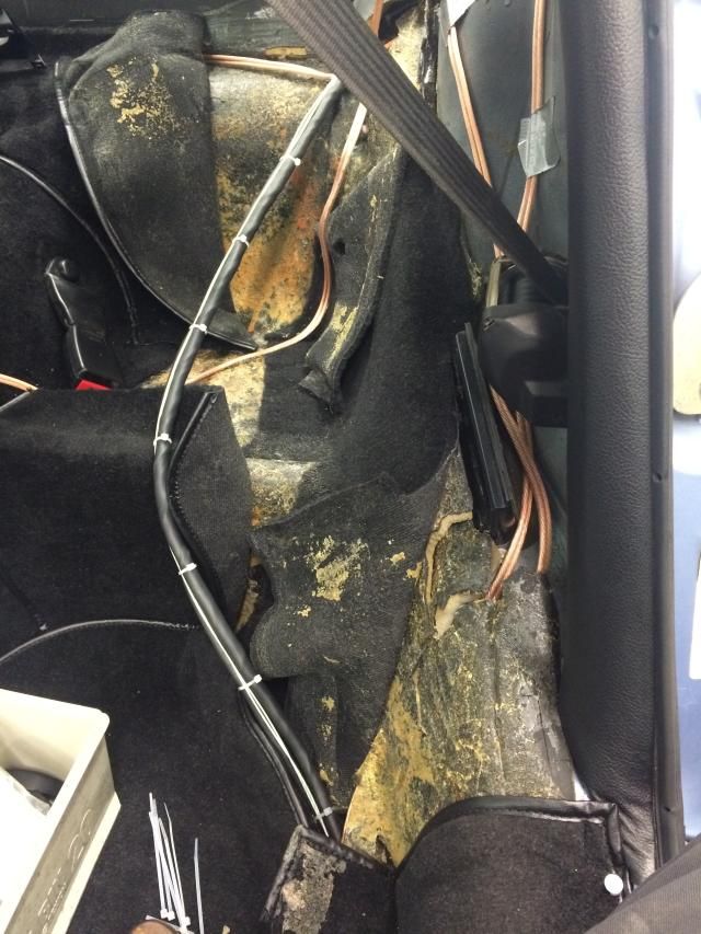  Talking of looms, I was relieved to see that the ECU > Engine loom should be millimetre perfect; That shouldnt be a shock considering the time weve taken to measure thrice and cut once however it was me that changed the plan with the routing once Simon had finished making the loom; changing my mind from the original plan of running it dirty side underneath the tinware through to the big grommet in the transmission tunnel (see above), as this would present challenges with fixing it in place, passing it though the tinware and risk of it getting damaged. I *thought* at the time that Id have too much loom to try and lose somewhere; as it happens, once routed under the sound deadening and using eyeball metrology, its just about spot-on .I hope. The antiquated 80s/90s immobiliser has now been completely surgically .removed. Harness now made-good again (some shocking examples of soldering more like arc welding with solder. How it lasted 20years without fracturing, I dont know). Some investigation into the latest/greatest immobiliser and tracking technology will be done over the Xmas break. The UK guys will be familiar with the Vecta style immobiliser key thats used, and the keyhole/socket it goes into, thats mounted in the lower half of the steering column shroud. Clearly this is removed with the rest of the immobiliser, leaving an unsightly hole. I may look to order a new shroud in the NY, but for the time being, I turned up a Nylatron bung to the exact ID of the hole, with a top-hat flange to set the depth. Its all now epoxyd in place, and I reckon looks pretty good as a temporary measure, the Nylatron being just a few shades off a deep black, thus matching the texture of the shroud nicely. 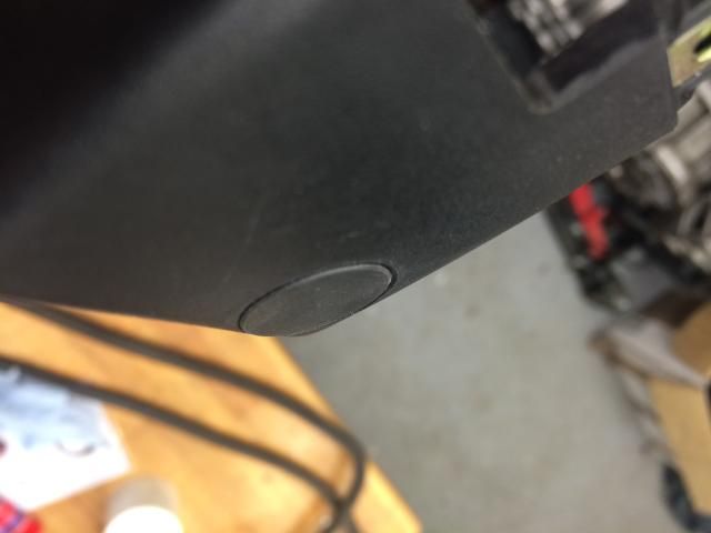 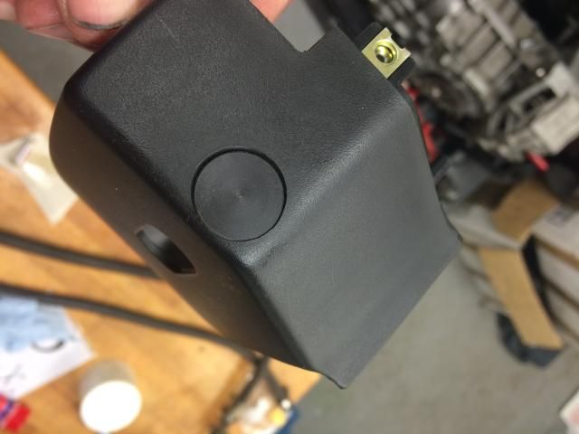 Another consignment of parts from OPC Tonbridge arrived this morning .all odds-and-sods, but stuff I can use to finish off a few more jobs: 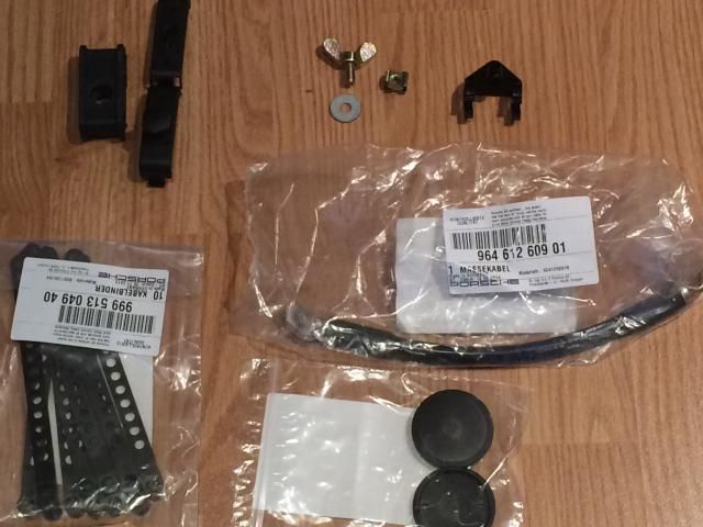
|
||
|
12-20-2014, 09:02 AM
|
|
|
Kartoffelkopf
|
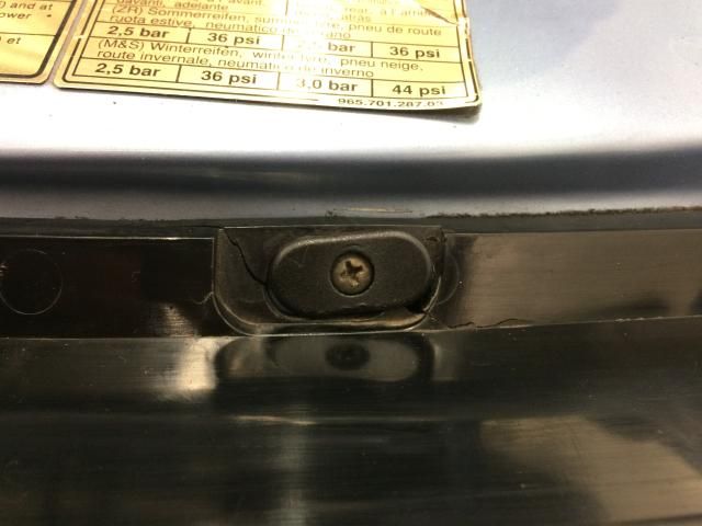
The rear RH lamp unit is back in, as-is the central reflector….kind-of. The only part of this car that wasn’t in good shape was this bit; all 3 mounting points are knackered, one is badly cracked but just about there:
 ...one is missing completely, nothing for the oval shaped caps to clamp against. There’s also splitting of the small 90deg return on the top edge: 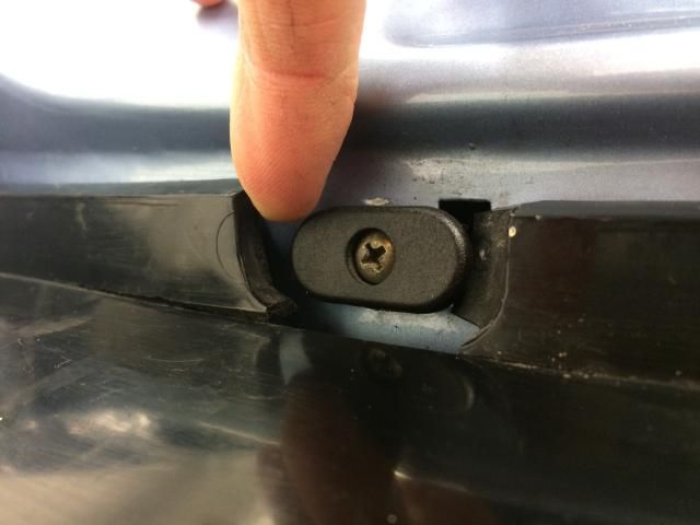 and the 3rd is somewhere in-between: 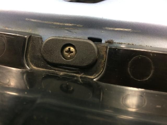 Hmmm. Can’t replace just the reflector as it will be bright red and will look rubbish against the now less than bright red rear lights. A new set @ £700 is a bit of a bitter pill, but it will look nice and fresh and give the car a new lease of life….get the Xmas expenditure out the way first, a purchase for the New Year. If I find myself at a loose end (fat chance), I may try and acquire some proper industrial grade superglue that’ll work with this grade of plastic, and see if I can have a go at fixing - nothing to lose, but in my experience, gluing plastics is generally unsuccessful - perhaps it’s just the cheap generic superglues I’ve always had to hand…. Anyway, looks nice now it's a bit more back together. Freshly painted engine lid and rear wing by my pal Shaun, and the rubber surround that's come up beautifully: 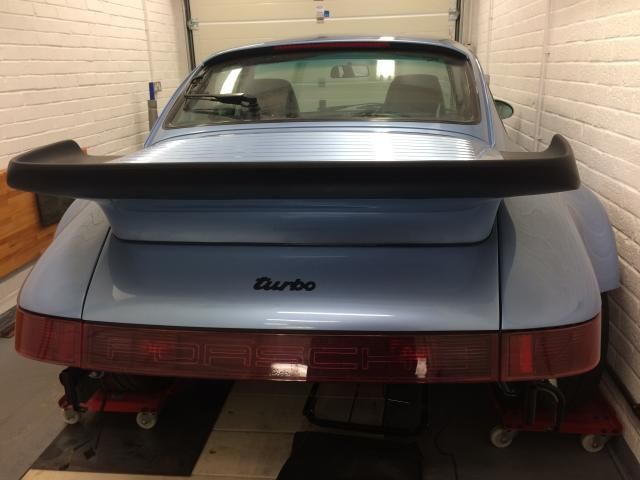 ***Watch this space if anyone needs to buy a pair of rear lamps that are in really nice condition, barely any spidering of the plastics.*** Question to those familiar with 964 Turbos….I can’t determine whether the rear lights should have the foil covered heat reflectors fitted…in the PET I can see the part numbers for the Carreras/Targa/Turbo-Look models, and I’ve seen one of the online vendors listing the same p/n for the Turbo also….but mine hasn’t got them. Can’t see any reason why it shouldn’t have them as well, apart from the different Turbo exhaust configuration perhaps not coming quite to so close to the back of the lamp buckets as the N/A models? Has a previous owner or tech removed and forgot to re-fit them previously, do we think? I think that’s it for now….tonights job is to start mocking up the a cardboard template for the speed sensors (think I said I was going to do that the other evening….oh well) The final auxiliary loom (that goes to the aforementioned boost/TC switches, the boost gauge and the warning lamp) is now also ready for sleeving and terminating. All measured and marked with the correct branching. Hopefully going over to Simons on Monday to get this done, as well as a new +VE power feed from the starter motor > the loom. Talking of boost gauges, my cunning plan is almost ready - it’s taken a long time to design it, engineer it, print it, etc, and if weren’t for a last minute shattering of the glass, it would’ve been ready yesterday…arggghh! So close, but is being finished this weekend. Very excited about this…more soon
|
||
|
12-20-2014, 09:06 AM
|
|
 |
|
|
| Tags |
| 964 c4/c2/turbo , efi conversion , life racing , syvecs , turbokraft |


 1993 Porsche 911 (964) Turbo 3.3
 2006 Lotus Exige Cup 240 (#45 of 50)
 BMW M2 Competition
 BMW R1250 GS Rallye HP
 Ducati 748R


 930
930
