|
|
|
|
|
| Author |
|
|
Heck, Im only 5 not 71!

|
Fixed VDO 461 Cruise Control Module
I have recently spent a lot of time working on the Tempostat Cruise Control Module for my 80SC in order to be able to understand it and hopefully repair the system. My cruise control would engage but not hold speed. In other words, as long as I held the Set/Accelerate switch up the car would accelerate but once released it would disengage. Researching this site and the internet provided a lot of useful information along with information that was not accurate for the module in my car. The Cruise Control Module in my 80SC has the following stamped on the case: 10.79, 12V, 412.203/1/10, and 928.617.127.00. The circuit board is a VDO 461 module and it does not match with any of the schematics that are available via the internet. Granted, there are several failure modes with suggested solutions so a schematic is not really necessary if you can locate certain parts on the module that are known to cause problems due to age of the components such as the electrolytic capacitors. I did all of the basic tests for the external switches and only had to adjust the clutch switch. I also removed and bench tested the tempostat servo motor with a 12 volt power supply and a vacuum pump. The servo motor checked out under vacuum and the servo solenoid engaged. So the only thing left was the tempostat cruise control module.
This is a picture of the tempostat cruise control 461 module from my car.  It is very noticeable that this module has two Quad Op-amps in the circuit where the available schematics for a similar module has only one Quad Op-amp and one single Op-amp along with a variety of components in different locations on the board. Since it is a 40 year old module that is no longer manufactured and no detailed tech data available we are left with not many choices for replacement or repair. Granted, there are several places that will for a very reasonable price will test and repair the module. As a DIYer my curiosity got the best of me so I set a goal to create a usable schematic and board layout for the circuit in order to troubleshoot and repair my own board. Yes, it would have been easier to send it off and have it repaired but there is no fun in that. I used a program called KiCad, it is a free software suite that features an integrated environment for schematic capture and PCB layout. Naturally there was a learning curve with using the program. The schematic capture requires that you manually add the components to a blank schematic and add the point to point connections of each component. Once the schematic is completed then the PC Board layout of parts and wiring ratsnest has to be done. It should be noted that I am not a design engineer so the schematic may not be laid out in the most efficient manner. Also, the KiCad program verified that I do not have any open ended components and it found no errors. The PC Board layout is not exact since the footprints are generic and not specific to each component. I was only concerned with getting the layout close to what the actual board looked like. I believe that the schematic represents the actual circuit board but I am the only one who reviewed it so their was no peer review. If you do notice an issue please let me know. I tested all of the components that were removed from the circuit board and only came up with three components that needed replacing. The two electrolytic capacitors C8 and C12 did not charge to the 47Uf capacity. Also the C20 capacitor is a small 68PF capacitor that I thought was iffy so I replaced it. All of the other components transistors, diodes, resistors and relays tested good. The module is now working and will set to the desired speed. It initially will cycle by about 2 miles below the set speed and then level out and maintain speed. I do have one issue with the zener diode D35 I cannot read the rest of the part number after ZTE, so if anyone can provide that part number it would be appreciated.       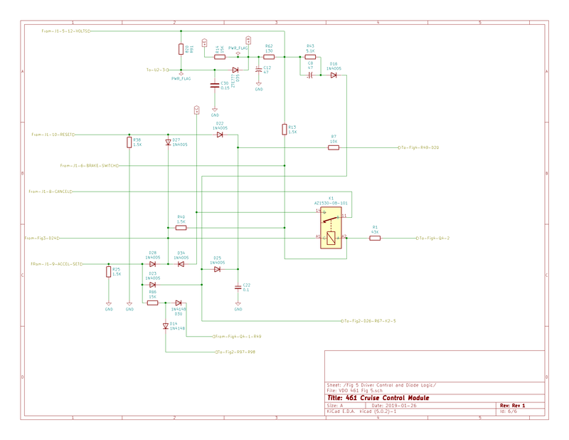  
__________________
Pat Henry Targa80 1980SC Targa (Mocha Brown) |
||
 02-25-2019, 11:29 PM
|
|
|
Registered
Join Date: Jun 2012
Location: Seattle, WA
Posts: 540
|
Damn, seriously impressed! This reminds me of what I used to love about his hobby before the run up in values that changed most of our conversations to ones about values, low miles, $1000 toolkits, et al. This will provide real value for those of us who value keeping all of the little systems on our cars working correctly. Thanks!
|
||
|
02-26-2019, 07:27 AM
|
|
|
Registered
Join Date: Jun 2008
Location: SE Pa.
Posts: 1,226
|
I bought my 81 in 92 from the original owner. The cruise control was already disabled - he told me that it had never worked properly. The dealer removed the solenoid and some other parts.
I had ambitions for a while of fixing it - I guess I have abandoned those. You have done a seriously impressive project.
__________________
1981 911 SC 2013 Mini Cooper JCW 2017 GMC K1500 |
||
|
02-26-2019, 07:43 AM
|
|
|
Registered
Join Date: Jan 2009
Location: Marietta, Ga (Atlanta)
Posts: 2,970
|
Great work! Any chance you could photoshop a red arrow pointing to the three components you replaced on the picture of the module. With the small print it's real hard to find the components on your board layout,
especially C20 (found C8 and C12). I have "fixed" several modules that had your same symptoms by removing the varnish coating on the back of the PC board and reflowing every single solder joint on the board (very tedious job). I took this path after I sent two modules to one of the EBAY fixers, and they came back with absolutely NO components replaced, but the board had had all the solder joints reflowed which "fixed" them and made them both operational.
__________________
'80SC Widebody 3.6 transplant Anthracite "The Rocket" Long gone but still miss them all: '77 911 Targa, '72 BMW 3.0CS Coupe(finest car I ever had!) '71 911T Coupe White, '70 911T Coupe Blue '68 911 Coupe Orange, '68 911L Soft Window Targa |
||
|
02-26-2019, 09:03 AM
|
|
|
Behind the Sun
Join Date: Jul 2014
Location: Tejas
Posts: 1,046
|
Impressive to say the least. Bravo. Amazing.
Getting so tired of spades on grills, instagram, patina on leather, hashtag, the right color, safari, oil type, flannel, 245/50/16 tires on the rear, etc, etc. Hats off to you Sir. Thank you. Last edited by 2.7RS; 02-26-2019 at 09:33 AM.. |
||
|
02-26-2019, 09:26 AM
|
|
|
Registered
|
Great,
I was doing similar work VDO Cruise Control Yet my problems returned, will have to replace the capacitors. I will try to get the zte diode reference |
||
|
02-26-2019, 11:37 AM
|
|

|
|
Registered
|
Any chance you are willing to share the KiCad files ?
|
||
|
02-26-2019, 11:41 AM
|
|
|
Registered
|
I have 3 cruise modules and all 3 work but not very well. All three modules exhibit the same behavior. They engage properly, for example I set the speed at 50MPH and it sets but then the speed drops off by 5MPH down to 45MPH then it slams the throttle and it picks back up to 50MPH then it repeats this nasty cycle 45-50-45-50-45-... very annoying.
I find it hard to believe that I have 3 modules all broken the same exact way? What I need is another car to test these 3 modules in. My car is a 1984 with the vacuum activated cruise. I also bench tested the Vacuum device on the bench with a hand vacuum pump and it does not leak. Thoughts?
__________________
Sal 1984 911 Carrera Cab M491 (Factory Wide Body) 1975 911S Targa (SOLD) 1964 356SC (SOLD) 1987 Ford Mustang LX 5.0 Convertible |
||
|
02-26-2019, 04:32 PM
|
|
|
Registered
Join Date: Jan 2009
Location: Marietta, Ga (Atlanta)
Posts: 2,970
|
Quote:
As I have noted in my previous post in this thread,I have fixed several modules by reflowing ALL the solder joints on the module. Just a "shotgun" approach I know but worked for me. If I knew the area on the board where the affected ckt was, it would make things much easier. I guess over the 30 or so years these modules have been around, the solder connections have in some way deteriorated and kinda act like a "cold" solder joint. Sal, I know you have a great deal of technical prowess, so why not clean off the varnish on the back of one of your modules and reflow the solder connections. I did mine under a big magnifier and bright light using a very sharp pointed solder iron and very, very fine gauge solder. Tedious job, but quite rewarding.
__________________
'80SC Widebody 3.6 transplant Anthracite "The Rocket" Long gone but still miss them all: '77 911 Targa, '72 BMW 3.0CS Coupe(finest car I ever had!) '71 911T Coupe White, '70 911T Coupe Blue '68 911 Coupe Orange, '68 911L Soft Window Targa |
||
|
02-26-2019, 05:28 PM
|
|
|
Heck, Im only 5 not 71!
|
Quote:
C20 is the 68PF cap that I was unsure if it was good (did not get a good reading on a capacitor tester). I have also highlighted cap C19. This cap is attached to MOSFET transistor M1. I have read that this cap becomes the standard voltage against which the cars throttle is controlled through the servo amplifier. I did not replace the C19 capacitor because it tested good. 
__________________
Pat Henry Targa80 1980SC Targa (Mocha Brown) |
||
|
02-26-2019, 07:27 PM
|
|
|
Heck, Im only 5 not 71!
|
Quote:
My only goal was to create a schematic for the sole purpose of troubleshooting my module. In order to create that schematic I had to reverse engineer the physical circuit board using the KiCad program and it took many hours over many days to complete. The KiCad program has the capabilities to create the schematic and the design template for the actual PC board that can be manufactured. With additional work on my files they could be used to create a new PC board so I will not be willing to share the actual KiCad files. I can convert them into a PDF file that would be usable as a schematic for troubleshooting and would be willing to email that to you.
__________________
Pat Henry Targa80 1980SC Targa (Mocha Brown) |
||
|
02-26-2019, 07:47 PM
|
|
|
Heck, Im only 5 not 71!
|
Quote:
__________________
Pat Henry Targa80 1980SC Targa (Mocha Brown) |
||
|
02-26-2019, 08:07 PM
|
|

|
|
Registered
Join Date: Feb 2014
Location: Lomita, CA
Posts: 2,726
|
Quote:
an alternator/charger as their rating is only 16 volts for the electrolytic ones (C8/C12).
__________________
Dave Last edited by mysocal911; 02-26-2019 at 09:08 PM.. |
||
|
02-26-2019, 08:32 PM
|
|
|
Registered
Join Date: Jan 2009
Location: Marietta, Ga (Atlanta)
Posts: 2,970
|
Quote:
__________________
'80SC Widebody 3.6 transplant Anthracite "The Rocket" Long gone but still miss them all: '77 911 Targa, '72 BMW 3.0CS Coupe(finest car I ever had!) '71 911T Coupe White, '70 911T Coupe Blue '68 911 Coupe Orange, '68 911L Soft Window Targa |
||
|
02-26-2019, 09:06 PM
|
|
|
Registered
|
Targa80,
a well readable PDF would be fine! I am just trying to fix my CC module as well (see post here ), had it working for 5 days, now it's back to 'not engaging'. I have been trying to do the same thing (I have 2 faulty modules) for my '85 Carrera, not trying to produce copies. After a year of working on the car to put everything back to original and in 'new' working condition, this is only one of the two problems I am left with (the other one is one headlamp washer not working) and I am sticking to doing all the work myself. BTW, I will open my spare box this evening to see if I can find out the label on the ZTE diode... |
||
|
02-26-2019, 11:57 PM
|
|
|
Registered
|
Quote:
|
||
|
02-27-2019, 12:01 AM
|
|
|
Registered
|
Quote:
As you can see in my earlier post ( here ) I am trying to fix my board myself. I am putting my car (85 Carrera) back to full original and after one year of working I have 2 'faults' left : the VDO cruise control not engaging 'on some days' and one headlight washer not working. Trying to do all the work myself, including the electronics. So a PDF with somewhat higher resolution (readable numbers) would be just fine for me ! I will open my CC box again tonight to get the label on the ZTE diode that you are missing, with some luck it is readable on mine. Frank |
||
|
02-27-2019, 12:05 AM
|
|
|
Caveman Hammer Mechanic

|
Hello,
In one of my previous posts, I replaced C8 and C12. The unit was dead as a doornail, when I replaced C8 and C12 it worked like a charm. Recently the unit still works but the speed slowly bleeds off. It makes sense that C19, being the reference for voltage, being old and possibly not working as well as it should, could be my speed bleed. Gonna bust out the Cruise Control brain, fire up my new Hakko FX888D-23BY soldering station, and start melting stuff. Any suggestions as to types of caps that might be a more modern upgrade? I could just match the old one, but how much fun can that be.... P.S. Paper on lifespan: https://www.illinoiscapacitor.com/pdf/Papers/reliability_of_capacitors_general.pdf
__________________
1984 Carrera El Chupacabra 1974 Toyota FJ40 Turbo Diesel "Easy, easy, this car is just the right amount of chitty" "America is all about speed. Hot,nasty, bad ass speed." Eleanor Roosevelt, 1936 Last edited by ClickClickBoom; 02-27-2019 at 11:03 PM.. |
||
|
02-27-2019, 12:26 AM
|
|
|
Registered
|
I have stripped the varnish and reflowed solder on 2 of the modules, same issue.
I also replaced those caps and a few others on one of the modules same issue. I need to find more time for testing but I think I need to find another donor test car to be sure I'm not chasing my tail with modules that are working and maybe the issue is elsewhere? I also notice that the problem with the 5MPH up down cycle seems to go away some if you pick a taller gear but I think that just masks the issue. Quote:
__________________
Sal 1984 911 Carrera Cab M491 (Factory Wide Body) 1975 911S Targa (SOLD) 1964 356SC (SOLD) 1987 Ford Mustang LX 5.0 Convertible |
||
|
02-27-2019, 04:41 AM
|
|
|
Heck, Im only 5 not 71!
|
[QUOTE=scarceller;103705.....
I need to find more time for testing but I think I need to find another donor test car to be sure I'm not chasing my tail with modules that are working and maybe the issue is .[/QUOTE] Chances are that the tempo stat servo motor is not a problem but it should be tested to eliminate it as a possible fault. Have you bench tested the tempo stat servo motor? You would need a 12 volt power source and a vacuum source such as a vacuum brake bleeding tool. I was able to verify my servo motor worked it held a vacuum once the servo motor solenoid was engaged. You can also test it with just the power source. You would need to cap the vacuum line and press down on the center of the rubber seal/cable connector. The seal should hold its position until you remove power front the solenoid.
__________________
Pat Henry Targa80 1980SC Targa (Mocha Brown) |
||
|
02-27-2019, 05:10 AM
|
|


 Porsche 911
 1984 Cab Factory wide-body (M491 option)

