|
|
|
|
|
| Author |
|
|
Kartoffelkopf

|
Quote:
 The Lotus is superb to drive, albeit not had it on the track yet...double adjustable Ohlins all round are screaming to be tinkered with, you even get documentation on Lotus' recommended settings for each of the UK tracks! It's the sort of handling I always tried to get out of the GT3, sharp and responsive at sane speeds, rather than having to drive like your hair's on fire for it to feel alive...likewise with the Westfield, I never quite got it to feel as lithe and "light" as a Caterham; the Exige is like that out of the box. Roll on the summer weather! 
__________________
1993 (MY92) 964 Turbo 3.3 - Horizon Blue - Follow my 964 Turbo project here... http://forums.pelicanparts.com/911-engine-rebuilding-forum/626572-964-3-3-turbo-efi-conversion-using-syvecs-life-racing-engine-management.html On Instagram (along with other stuff) as @spenny_.b #spennybengineproject |
||
 04-25-2014, 06:37 AM
|
|
|
Kartoffelkopf
|
Quote:
Funny you mention about sharing the project - I recently joined a (very well known) Open Source software company, and the whole ethos and culture here is one of the greater-good, the community, anti-proprietary, freedom of choice and importantly feeding back knowledge and technologies back into those communities....I guess this project is my own little bit of "open source" give-back...albeit pre-dating my move here by a few years! Quote:
The Blow Off Valve (BOV) is used to quickly dump pressurised air on the event of shutting the throttle, ie a gearchange or lift off. Again, you can imagine the situation where the pressurised gas from the turbo compressor has been fed through the intercooler, on its way to the throttle body and inlet plenum. When the throttle is closed, that pressurised gas then needs to go somewhere or else the intercooler is going to rupture, or the throttle won't be held shut! Production cars recirculate the charge (nice and quiet), whereas this method is to dump to atmosphere (the sneezing or chirrupy noise that you often hear on tuned engines). HTH S
__________________
1993 (MY92) 964 Turbo 3.3 - Horizon Blue - Follow my 964 Turbo project here... http://forums.pelicanparts.com/911-engine-rebuilding-forum/626572-964-3-3-turbo-efi-conversion-using-syvecs-life-racing-engine-management.html On Instagram (along with other stuff) as @spenny_.b #spennybengineproject |
||
|
04-25-2014, 06:50 AM
|
|
|
Kartoffelkopf
|
Evening folks, time for my once-a-month check-in!
Been very busy getting the garage and barn cleared of the old Westfield parts - the local Post Office practically offer me a cup of tea each time I go in there, such has been the regularity (and the amusement with wrapped rollcages, and odd looking exhaust silencer packages!) So, clearing the decks has been the order of the day. Finally got around to returning to the engine project; although nothing worthy of photos at the moment, this is what I've been working on.....
Now, something else I've decided upon is to forget the idea (for the time being) of water cooling the wastegates and turbo. In some respects it was complete overkill anyway, strong case of "while-I'm-at-it-itis", but frankly, I'm struggling to see the light at the end of the tunnel with this project; "losing the will" is perhaps too strong, but it's certainly feeling like a slog and ever so slightly daunting with the amount of sub-projects to get done. On top of which, the radiator I bought as a bit of a punt is nowhere near fitting, just too big to squeeze into the LH area behind the A/C rad. I'll keep all the hosing, and will still have the loom made to accommodate the pump and sensor so that if I do need to use it, it's there in readiness....very much a case of the K.I.S.S. principle. So...that's the latest, will be posting pics when I have them. Last edited by Spenny_b; 05-24-2014 at 04:24 PM.. |
||
|
05-24-2014, 04:21 PM
|
|
|
Moderator

Join Date: Dec 2001
Posts: 9,569
|
Remember Spencer, that when Sir Edmund Hillary neared the Summit, there was Tenzing Norgay at his side! WE are your Sherpa. . . WE are with you as you step higher and higher!
And now some comments: 1) All Porsche projects eventually become infrastructure projects; which includes the shipping out of bits of past projects! 2) Throttle linkage good! Intercooler removability better! These are the little things that take a GREAT deal of time. But I know you won't rush at this stage and will take time to do them right, like you are never going back in there! 3) Fuel lines, and running them through the tunnel in a way that neither hacks the original chassis nor creates any interference problems, are an area where I have some experience. That experience says: run the Factory lines if at all possible without introducing too many connections (AKA failure points) into the mix. I spent a bloody fortune on Aeroquip startlite hoses, -6AN connectors, the special wrenches, 90s, adapters and the other chingaderras like I was plumbing up the Space Shuttle. In retrospect I spent WAY too much time making it complicated. Also, the factory bits are engineered for the vibration resistance etc. that would give a great deal of confidence when you are doing the ton. 4) Wiring loom. The hard part is already done-- the design phase. Most guys here start by building the loom, then figure out the design. You have the best part-- a diagram already there, to make future troubleshooting possible, maybe even easy, for when the inevitable square electrons come up. I waste a lot of breath here trying to tell guys to NOT modify their original electrical system to "improve" it without documenting every step. . .years later people will come on here and say, "I am having electrical problems" and then after about the fifth post, will say, "Oh I forgot to mention that the car has modified wiring." It's hard enough to diagnose electrical issues when you're standing right there. . . over the Internet? Impossible. Rant over!  HIDs. Why give the constabulary a reason for an impromptu chat? I say, revert to stock units with proper relays and wiring and the best bulbs, and consider some aux lamps if you really find you're overdriving at night. This is all good progress! And you have come a long way. In terms of water cooling. . . I think you owe it to yourself to commit to "finishing" by a date certain so you can enjoy the car, then reserve certain projects for Winter. Without a doubt, the motor will have to come back out at some point by your own choice-- there will be this and that that you will want to do differently-- aggregate all those items into a big list to tackle at once in the off-season. This is precisely what I'm doing with '065-- put it all together, then take it apart again to fix all the things where it could be more perfect. . . or where my knowledge and taste has evolved since I started the project! Looking forward to the pics, Cheers!
__________________
'66 911 #304065 Irischgruen 96 993 Carrera 2 Polarsilber '81 R65 Ex-'71 911 PCA C-Stock Club Racer #806 (Sold 5/15/13) Ex-'88 Carrera (Sold 3/29/02) Ex-'91 Carrera 2 Cabriolet (Sold 8/20/04) Ex-'89 944 Turbo S (Sold 8/21/20) |
||
|
05-27-2014, 10:15 AM
|
|
|
Kartoffelkopf
|
Quote:
Quote:
Quote:
Quote:
There's a guy (Rob) here in the UK who's done an outstanding 964 Carrera resto, documented over on RennList (and mentioned a page or so back)...he went the route of -6 lines for fuel, rerouting it slightly different from stock, but still down the tunnel, no cutting or drilling and looks very good; I'm going to have another look this evening and decide either way. Quote:
Quote:
Quote:
Sage advice, and indeed, the engine is likely to be dropped again once it's run-in to set valve clearances (although I may well treat myself to the setting tool in the other thread - looks very nice) Quote:
Quote:
|
|||||||||
|
05-27-2014, 01:28 PM
|
|
|
Kartoffelkopf
|
Some pics of the throttle linkage -->
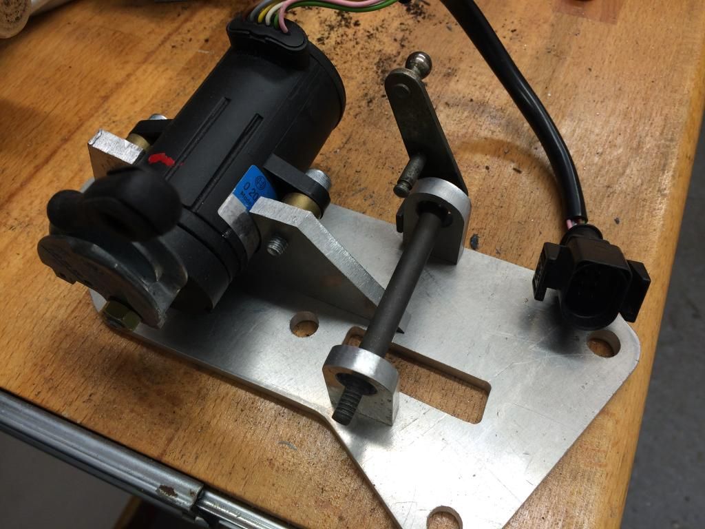 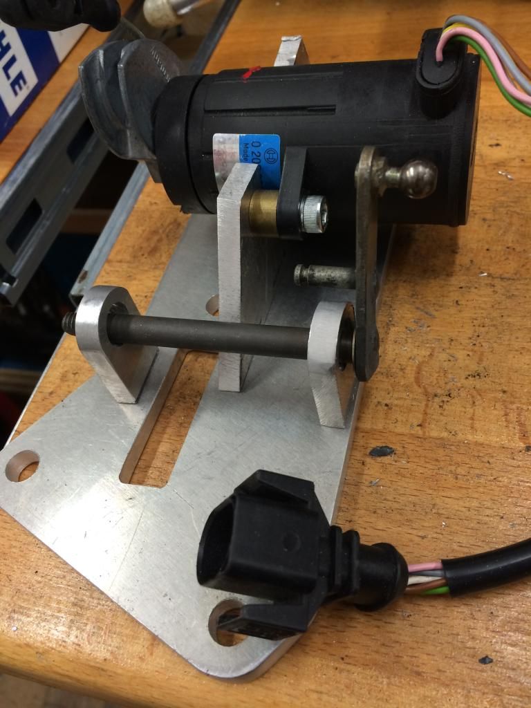 Component parts are obviously just balanced on the bench, but you get an idea of the approach I'm taking. Ignore the rectangular hole in the middle; that was from Plan A when I was thinking about making a plate that sat on top of the original unit. Not going that route now, but when all welded up, the centre section will be milled out to remove that rectangle (and make it fractionally lighter!) Trying to keep as many of the dimensions and geometry the same as stock, to ensure that there aren't too many variables that could mess things up later on (i.e., not getting full throttle travel) The spindle in the pics won't be used - I'll make a similar one, maybe out of stainless, that'll run in oil-lite bushes. Another reason for keeping the stock dimensions, even for teh pillars, is that the vertical plate on that spindle has a throttle return stop that butts up against the pillar on shut throttle; will incorporate the same technique on mine. All looks remarkably simple, but making sure that all the angles and travel lengths are right is quite a time consuming exercise. Fingers crossed it pays off. |
||
|
05-27-2014, 02:05 PM
|
|

|
|
Kartoffelkopf
|
Here you go guys, the post in Robs thread I was referring to with regards to new fuel lines -->
Rennlist Discussion Forums - View Single Post - 964 Refurb (have just enjoyed re-reading a lot of Robs thread, some really great ideas in there....the whole thread is here if you fancy a decent read
|
||
|
05-27-2014, 03:52 PM
|
|
|
Registered

Join Date: Mar 2005
Location: Phoenix, AZ
Posts: 2,862
|
Quote:
Measure your time & effort vs. cost but bolt-in...   
__________________
Chris Carroll TurboKraft, Inc. Tel. 480.969.0911 email: info@turbokraft.com http://www.facebook.com/TurboKraft - http://www.instagram.com/TurboKraft |
||
|
05-27-2014, 05:00 PM
|
|
|
Kartoffelkopf
|
Hi Chris, and thanks!
Decided today to go with -6 flexible lines, the same material as I've used on the engine; minimises the number of junctions, and with some decent stainless/rubber P clips, I should be able to tether it along the length of the tunnel. Progress this evening! The old fuel lines are now out - a little bit of a wrestle to get them past the LH suspension (the car is still up in the air on the floor lift, the frame of which does hinder the space under the car a little) 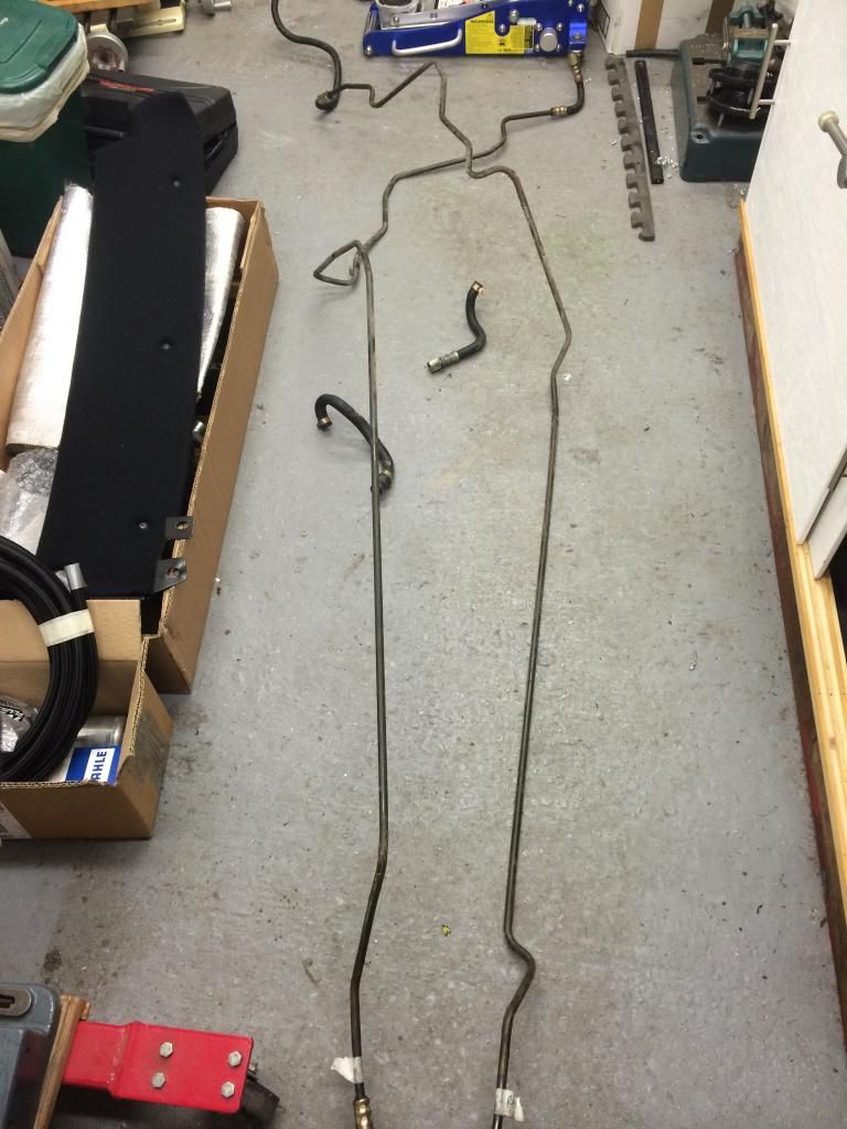 Glad I didn't re-use them; found a few spots where rust had set in quite badly. Overall, my car's in very good condition rust-wise (for the UK)....when I compare it to some of the challenges that Rob had with his resto (linked above), eg, the fuel pump cubby hole, mine is mint condition with a lot of the Dinitrol brown waxy stuff still on there...but even so, the fuel lines had started to deteriorate, so any UK guys reading this, thinking that their cars are equally rot-free, please do have a very good look in all the hidden, inside bends of those lines. 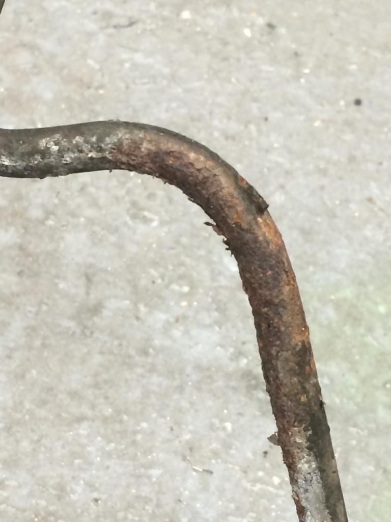 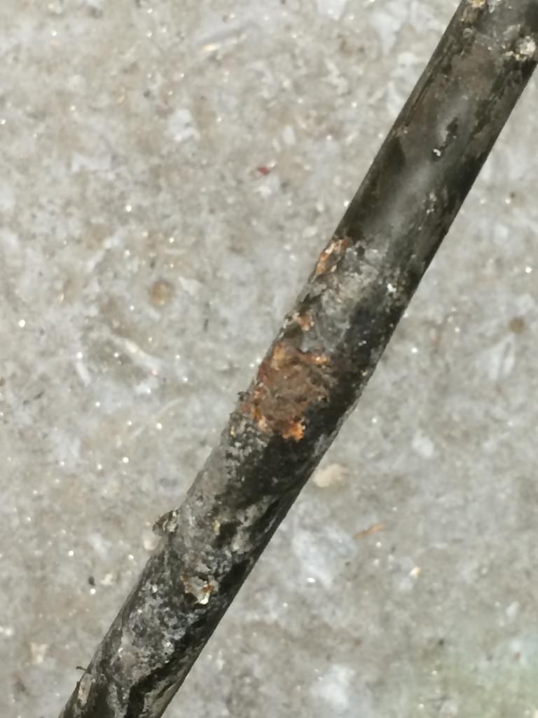 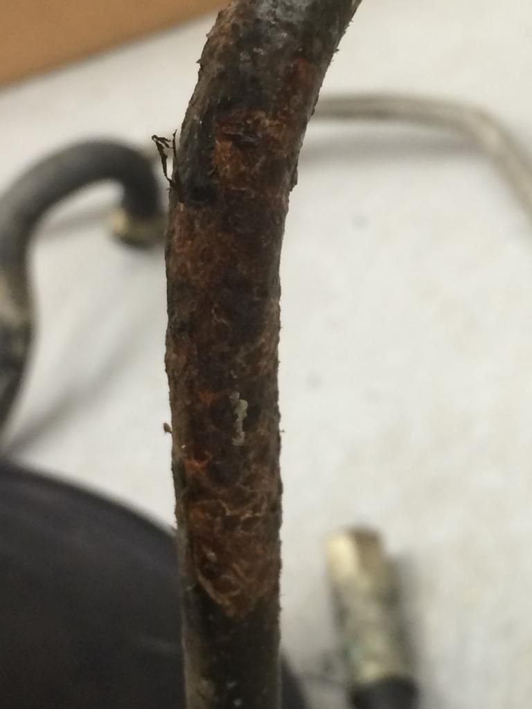 Fittings from Think Auto are sorted; a fair size bill but still cheaper than replacing the OEM lines like-for-like (about half the cost)...just need to order the 2 hoses that link the tank O/P to the pump intake, and the return line back into the tank. Looking forward to getting the pumps and filters in place, then hooking up the lines and fixing it all in place, and finally putting some stuff back ON to the car (fuel pump hatch cover)...probably won't be this weekend though - time to take a brave pill and remove the front clamshell from the Exige to (pre-emptively) replace the (known weak) radiator....am journeying down to Le Mans to see Porsches return to the top class, and sods law dictates that the usual queueing at the tolls, in the inevitable scorching (!) weather, will cause the brittle plastic end tanks to let-go...so, time to fit a nice new thicker core ally unit and silicon hoses. Gulp. Last edited by Spenny_b; 05-28-2014 at 04:27 PM.. |
||
|
05-28-2014, 04:22 PM
|
|
|
Kartoffelkopf
|
Fuel system fittings....
A quick pic of the parts from Think Auto for the fuel system....just need to order two new hoses that interface directly to the tank (outlet>pump#1 inlet.....and then the return line > tank)
However, one of those hoses is now NLA.....how can only one part of the whole system be made NLA, its a simple bloody piece of hose with a swaged on metric fitting!....the same as the rest of the system!....daft, nevermind, plan B time; will just need to order some -8AN hose with a -6 interface to the line that returns back from the engine. 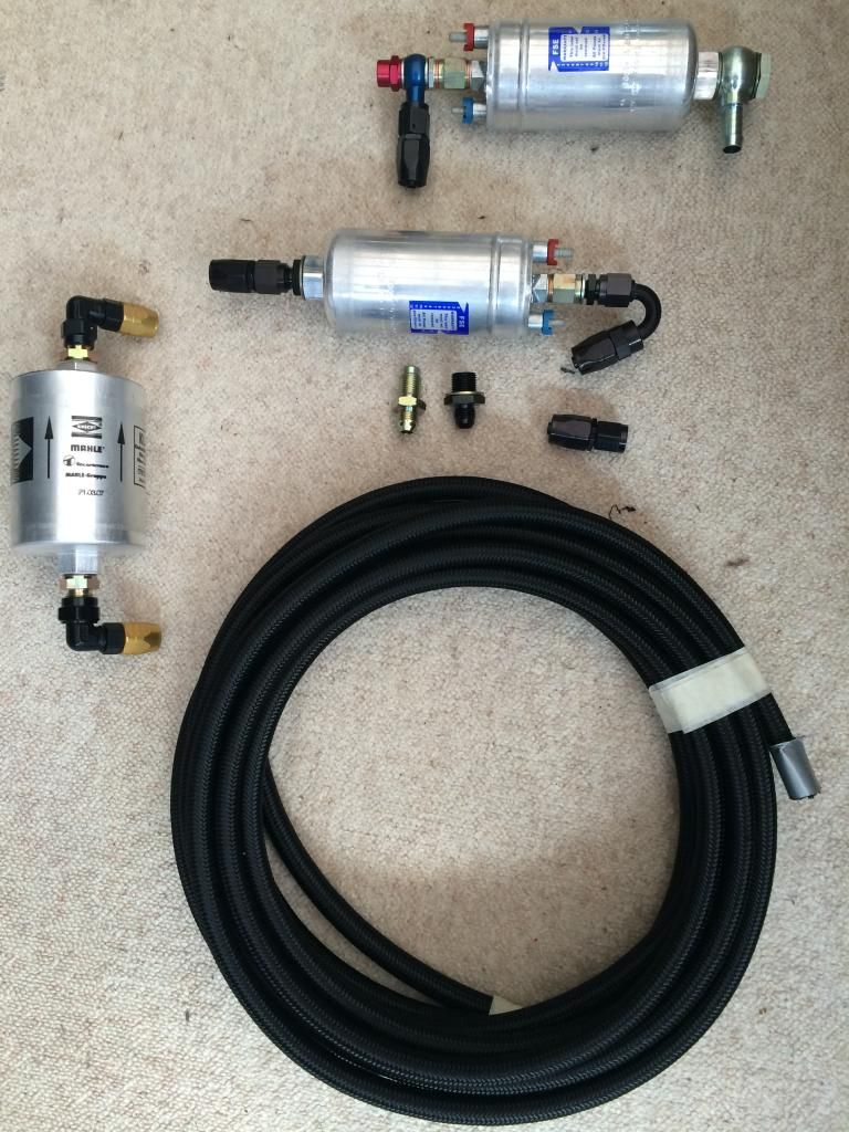 Still amazed at what you don't get for almost £230! (I already had the 2x 044 pumps and the filter) |
||
|
05-30-2014, 10:41 AM
|
|
|
Kartoffelkopf
|
Throttle Linkage
Evening all,
Time for a check-in. Great weekend's progress....distinctly average weather and a weekend to myself allowed me to lock myself in the workshop to crack on with the job I've been naffing about on for ages...the throttle linkage. It's another case of "I can't believe it's taken this long, with not a lot to show for it". After a significant amount of time spent pondering, measuring, experimenting and generally not getting very far, I ended up Saturday evening a little miffed that another progress-light weekend was about to happen. BUT!...today, with the replay of the MotoGP (Assen) and watching the Le Mans 24hr coverage I'd recorded (yes, I know....very sad to have both gone there, and also recorded it, but you know how it is....) on the TV as background entertainment, I've almost finished the linkage. For the first time, I rigged up my pillar drill as a lightweight mill. I have no real need for a dedicated mill, I don't do that much hardcore milling (although that'd never prevent me from justifying getting one in the workshop), so I bought an X-Y table a few months back. With some rigging up, I was able to machine the redesigned central pillar for the pivot bar, ensuring that everything's square:   It worked really well! Obviously I didn't take big cuts, and the speed selection is rather limited by the 5-spd pulleys, but pretty chuffed how it all came out. 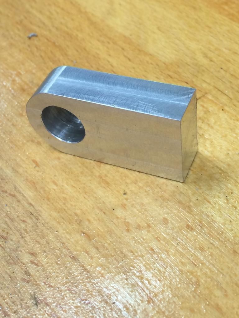 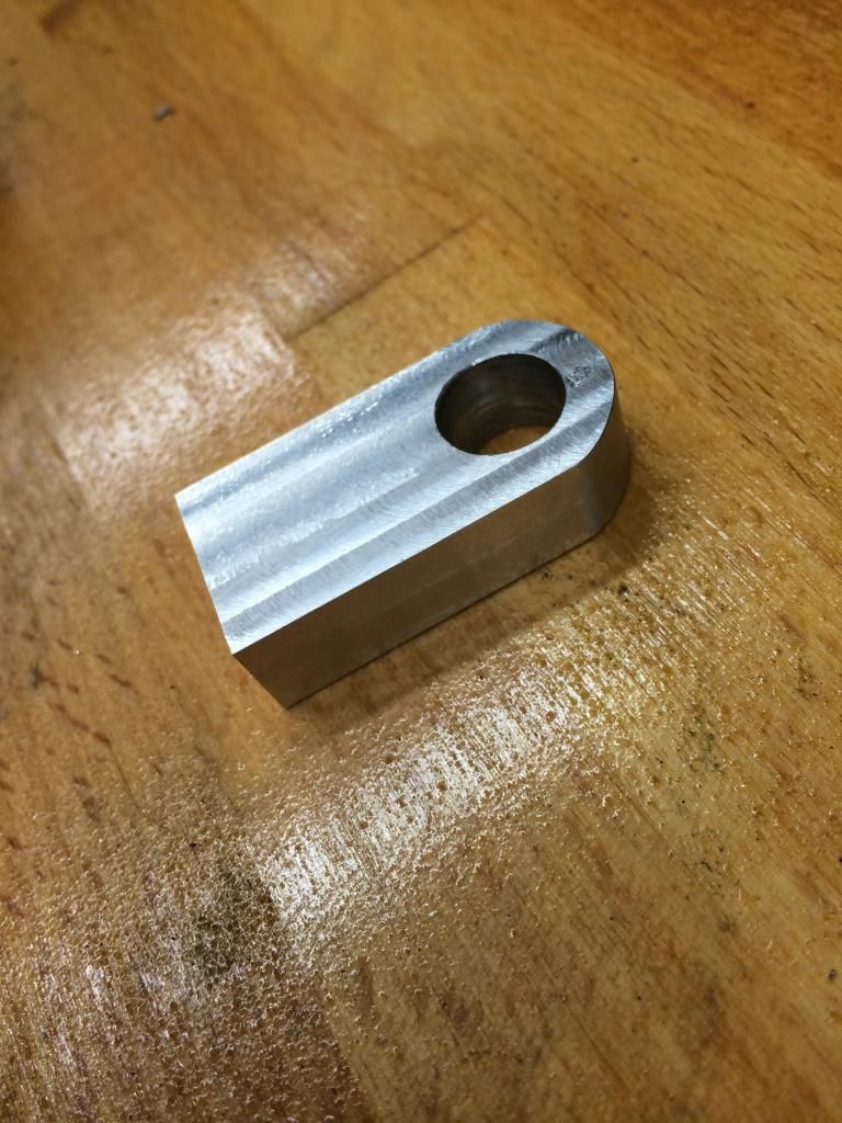 Also made some adjustments to the potentiometer mount, specifically I trimmed it down a little, got the edges square to ensure correct alignment when we weld it. Finally, replicated the pivot arm that the original linkage uses, except reversed. This is the sort of thing that takes the time, ensuring that the dimensions are the same as the OE unit, thus full throttle travel is still OK, but also then working out the max travel of the potentiometer, doing some trig, accurately marking it up and drilling. Also had to ensure the throttle stops were identical....almost finished, got the throttle cable ball joint in (new), just need to turn up a shouldered spigot for the potentiometer to mount on, make the pivot bar itself (the one in the pic is just a piece of 8mm stainless I happened to have). 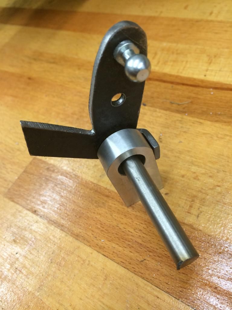 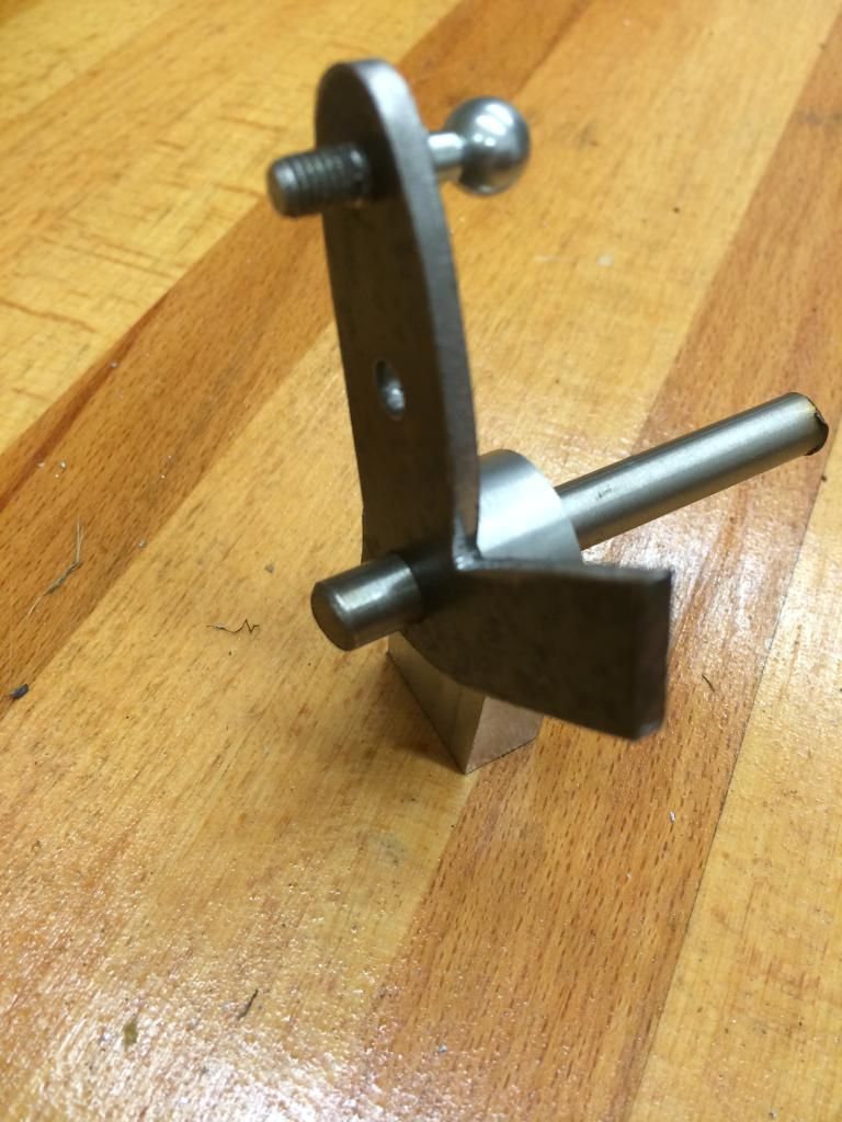 And this is how it's going to all mount: 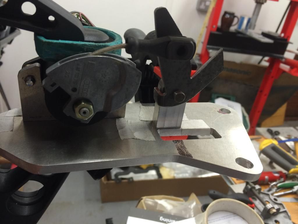 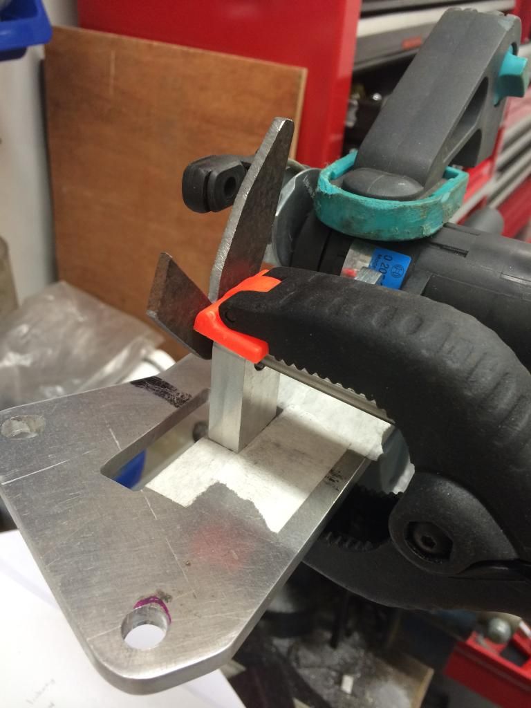 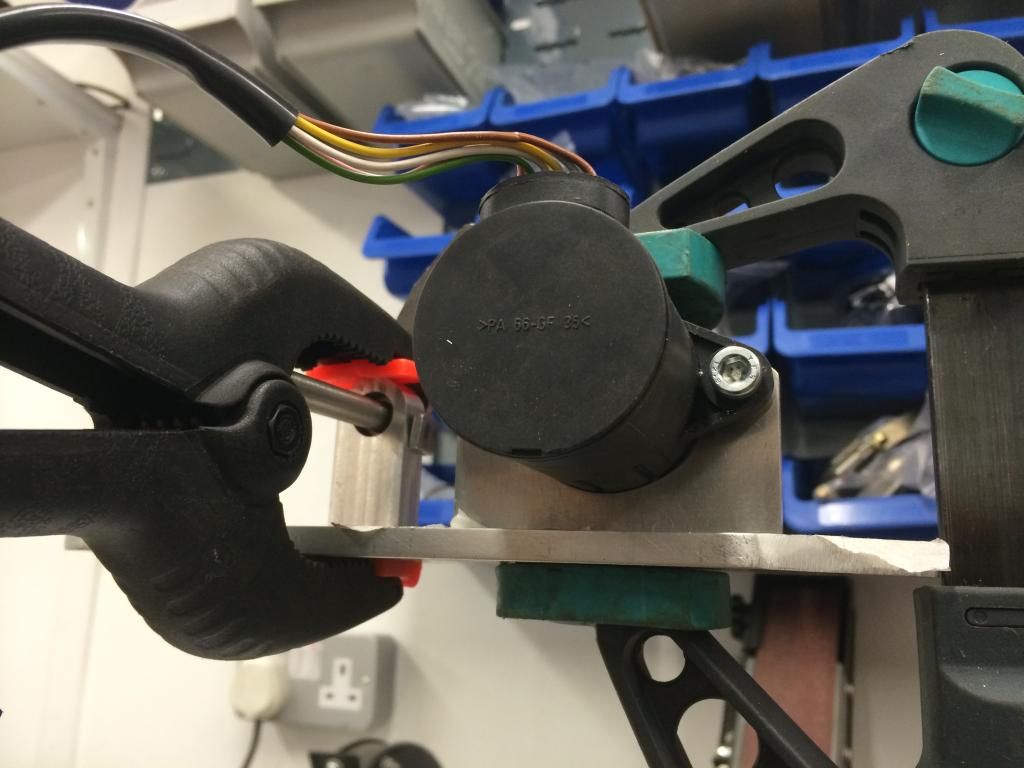 So, there you have, an unfeasibly small part of the overall project taking a disproportionate amount of space in this thread! But if eThrottles ever catch-on with these sort of EFI conversions, hopefully somebody can find this design useful. In other news, wiring loom diagrams have been sent to me, but quite a few corrections need to be included before it get's made. And on it goes.... ")
|
||
|
06-29-2014, 04:32 PM
|
|
|
Kartoffelkopf
|
Ok, another minor update - spent some evening hours getting the throttle linkage ready for welding on Saturday morning; all went well, another sterling job by the boys at Fabweld!
Then last night, time to start lightening it a smidge, polishing it a little ready for final finishing. Still undecided as to whether to black anodize it (favourite option), vapour blast it to try and get it looking as OE as possible, or just leave it polished per below (but may look rubbish in years to come, without any protection on it) 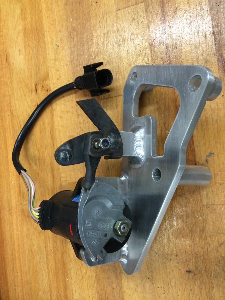 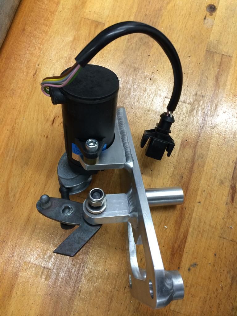 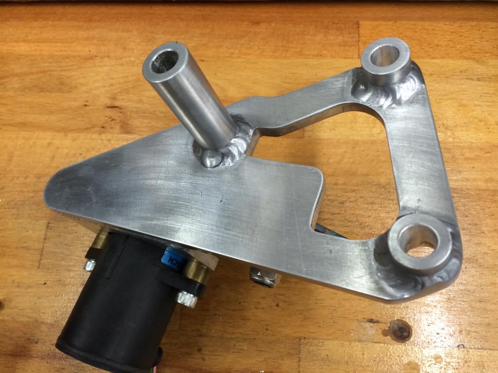 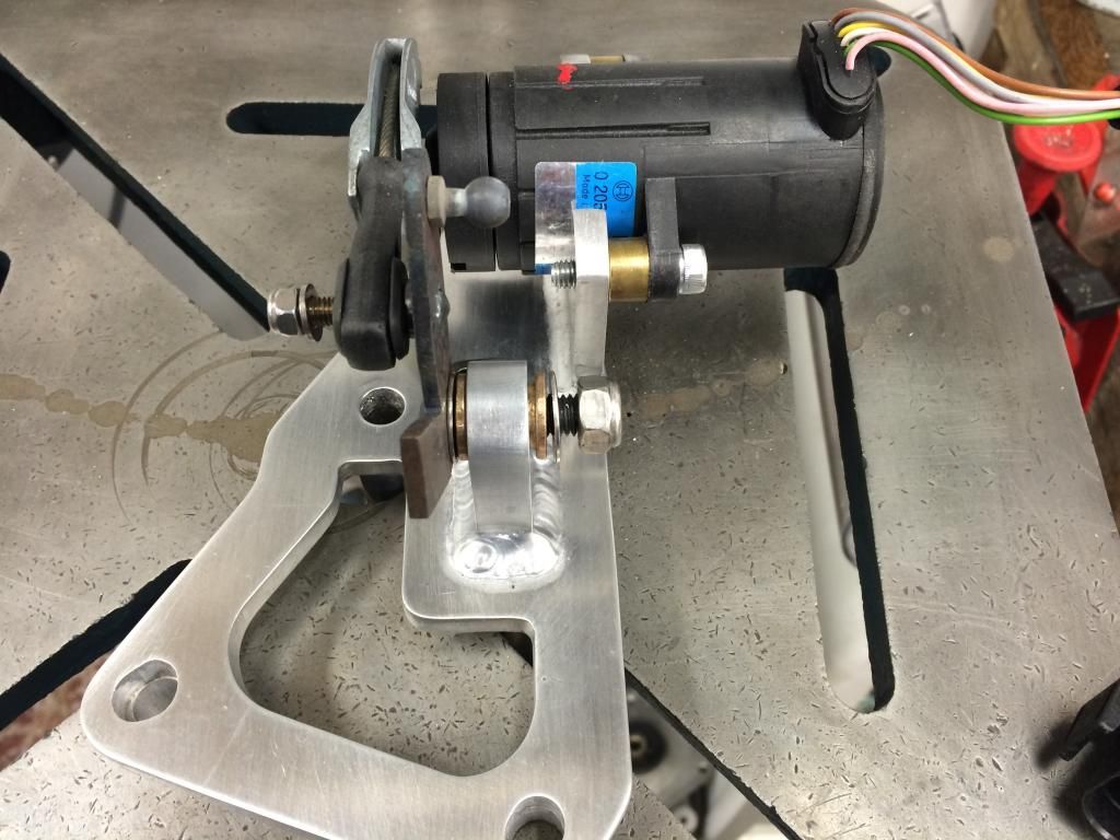 Clearly the actuating arm needs plating; I'm not convinced I've got this part *quite* right just yet, insomuch that the max swing movement of the original lever is 55mm and the new one is only 45mm. Now, whether I can accommodate this with the rest of the cable setup, I need to evaluate, but may need to resort to trying to modify this one, or if I can be bothered (!), make a new lever, pivot shaft and eThrottle pivot shaft. The throttle-stop also needs to be made, however I decide to do it. The oil-lite bushes also need to be shortened to accommodate the width of the single pivot pillar. All-in-all, very happy with it though; no flexing, twisting or anything funky that's likely to screw-up mapping due to unpredictable actuation. On another subject, hoping that the wiring loom guy can come over this coming weekend to have another look-see; we agreed the other day that it's over 1.5yrs since he originally visited to make the mock-up loom; I'm now a lot further along with the build, he's made changes to the way he manufactures and branches the loom out, and we *may* be able to route the harness slightly better through the tunnel aperture, rather than drilling a bloody great big hole in the seat-back bulkhead.....applying the principle of 2 heads are better than 1, then hopefully he can kick this straight off into some manufacturing activity. |
||
|
07-07-2014, 03:22 AM
|
|

|
|
Moderator
Join Date: Dec 2001
Posts: 9,569
|
Forgive me Spencer, but if the max swing of the throttle arm is shorter by 10mm, won't that limit the power setting? Seems to me you want it to be identical to what the factory did. Why is the arm L-shaped, is that a stop? Will the stop be adjustable?
I definitely would not leave it bare metal given your mediterranean climate. Anodize would look good and it would also help in the areas most likely to corrode-- under the bolt heads and in the holes, when the dissimilar steel bolts start working against it. I don't expect you will be splashing much water up there but it's one less thing to worry about. Looks GREAT! The last 10% takes 90% of the time. Glad to hear of progress with the wire harness. These jobs are simply a matter of making a bit of progress every week. Trust me, you won't want to go back in there when it's driving.
__________________
'66 911 #304065 Irischgruen 96 993 Carrera 2 Polarsilber '81 R65 Ex-'71 911 PCA C-Stock Club Racer #806 (Sold 5/15/13) Ex-'88 Carrera (Sold 3/29/02) Ex-'91 Carrera 2 Cabriolet (Sold 8/20/04) Ex-'89 944 Turbo S (Sold 8/21/20) |
||
|
07-18-2014, 05:53 PM
|
|
|
Kartoffelkopf
|
Quote:
Am going to either make a new linkage or modify the existing one....now that I have a new set of carbide tipped lathe tools (which arrived this week), I may be bothered and make a new pair of spindles. Quote:
Quote:
Quote:
|
||||
|
07-19-2014, 04:53 AM
|
|
|
Kartoffelkopf
|
Oil pipes etc
Have now got a lot of the pipes I'd taken off the car re-swaged with new hosing by the guys at Think Automotive...another top-job.
The turbo oil scavenge pipe: 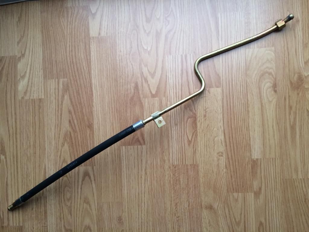 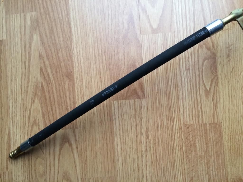 The oil thermostat > engine pipe that sits in the RH wheel-arch: 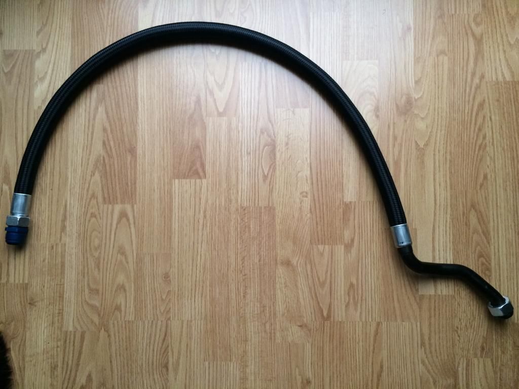 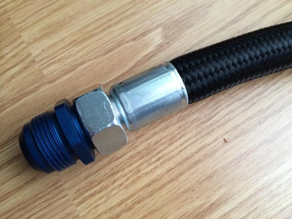 The 2 x oil lines that go form the thermostat > oil cooler: 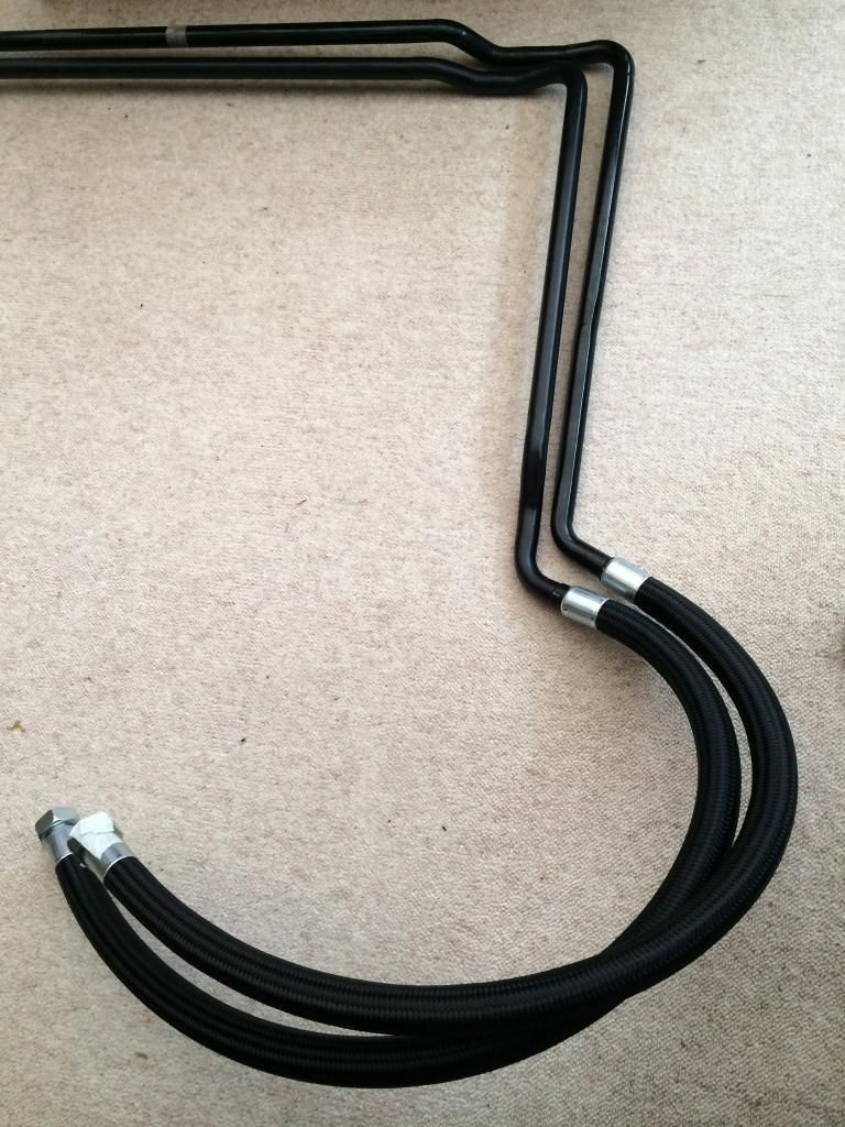 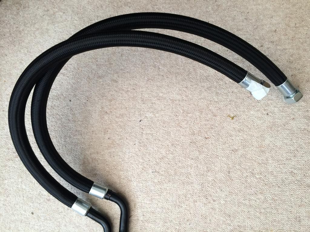 Plus, I've got the kit I need to make up a new line that interfaces the engine to the above wheel-arch/thermostat line. The original line is a 3-piece affair, with fairly complex bent rigid lines joined by a 8-9" flexi section, which routes it's way around the engine, under the heat exchangers, etc. When I cleaned up the sorry looking line a couple of years ago, it was very pitted and had what looked to be a poorly modified bend that goes into the crankcase - insomuch that the 90deg bend had looked to be collapsed on the inside of the bend, with some ad-hoc welding...deffo not original Porsche, and limiting oil flow. A new line? £342+VAT!!!...plus, there's no guarantee that it'll actually now be correct for the new engine; e.g., the old one passed over the exhaust valve cover on one side. However, I'm now running 2 plugs/cylinder with coil-on-plugs, so, could easily have found that the rigid part of the line now fouls them, or maybe even runs where I've made my new oil catch tank for the turbo drain, or any of the additional items on this build. The answer? Buy some -16AN Aeroquip with some very nice angular fittings, and make the line as a single piece, routing and mounting as appropriate to clear anything that's now in the way: 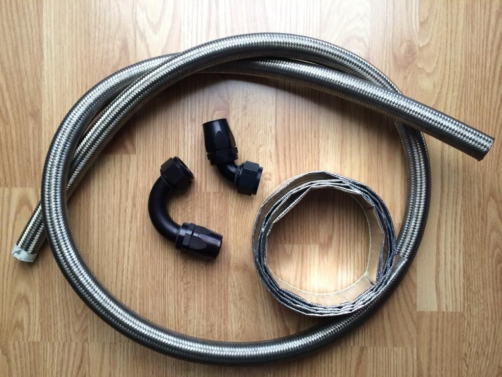 All the rubber hoses from the dry sump tank to the engine will also be replaced; there a siamese hose that returns from the chimney to the top of the tank on the 964 Turbo which is an annoying £250 but the rest are between £15 and £30 each....still extortionate for a lump of rubber hose; funny how you get used to Porsche pricing to the point where £30 for a hose seems reasonable! Turning my attention back to the fuel lines, there was one hose I had to partly destroy to get it off the tank; the fuel return line > tank is a short rubber line with a swaged metric fitting to join to the rigid fuel line that comes from the engine bay....it's the only hose of all the ones I need, that's NLA from Porsche. Terrific. Not to worry, another solution from Think Auto, using some wrapped heavy duty 10mm rubber hose with a Metric > -6AN fitting on the end that'll then link up to the -6AN line that'll run to the back. This seems to be a good option; the -6AN fuel line is too small to go onto the tank inlet (10mm), plus by maintaining the Porsche way of doing it, and not having the return line going directly onto the tank, I can then remove the tank easily by just uncoupling the -6 fitting under the car, rather than fight the a clamped on connection up in the fuel pump/tank recess. 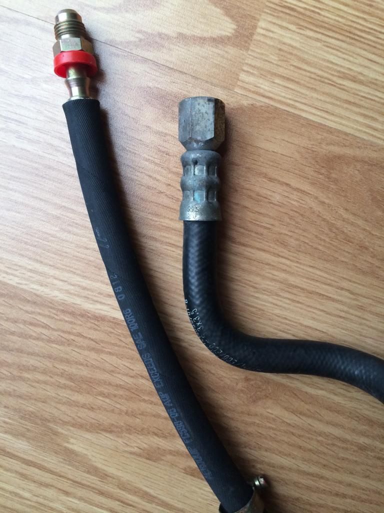
|
||
|
07-19-2014, 10:59 AM
|
|
|
Kartoffelkopf
|
Exhaust backpressure monitoring
Another inclusion to the "rolling lab" is something that Chris @ TurboKraft had mentioned a while ago was trying to include the ability to monitor the exhaust backpressure (EBP). To be honest, I'd not turned up too much when looking for sensors online, so had mentally parked this idea for the time being...and then...
When searching around for a suitable interface to feed the ECU with exhaust gas temperature (EGT) readings, I also found that AEM do a kit that remotely mounts a high quality pressure sensor away from the manifold, using a combination of rigid and flexi lines. However, their kits are $260 each plus the shipping, tax, etc, and of course, I'd need two of them. Time for another plagiaristic apology; having access to a great plumbing and fittings supplier, I reckoned we could make our own for a lot less. Sure enough, Think Auto had some -3AN (3/16") stainless steel tubing, the Teflon lined flexi piping plus all the -3AN fittings to take a feed from the manifolds to a pair of F1 grade sensors from SBD that match the oil and fuel pressure sensors used elsewhere on the engine. These are proven sensors that are completely linear in their operating range (0-150psi), something that's extremely hard to do (and generally never delivered against in lesser sensors); thank goodness for commodotisation (sp?), as these used to retail for in excess of £400 each a few years ago - now comfortably under £100. 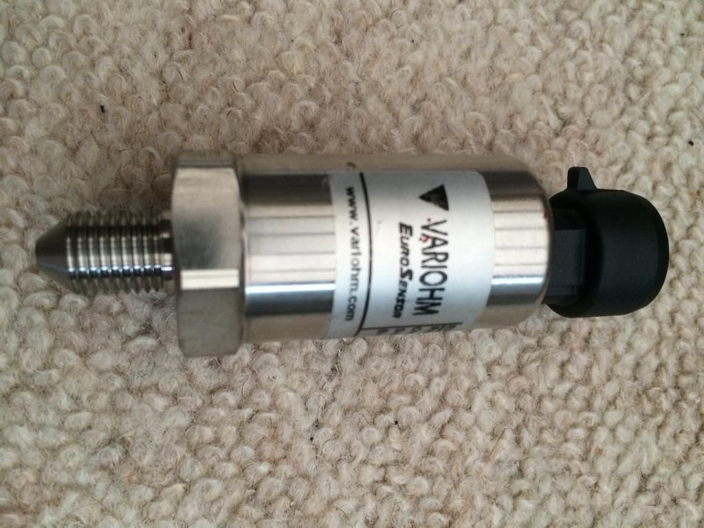 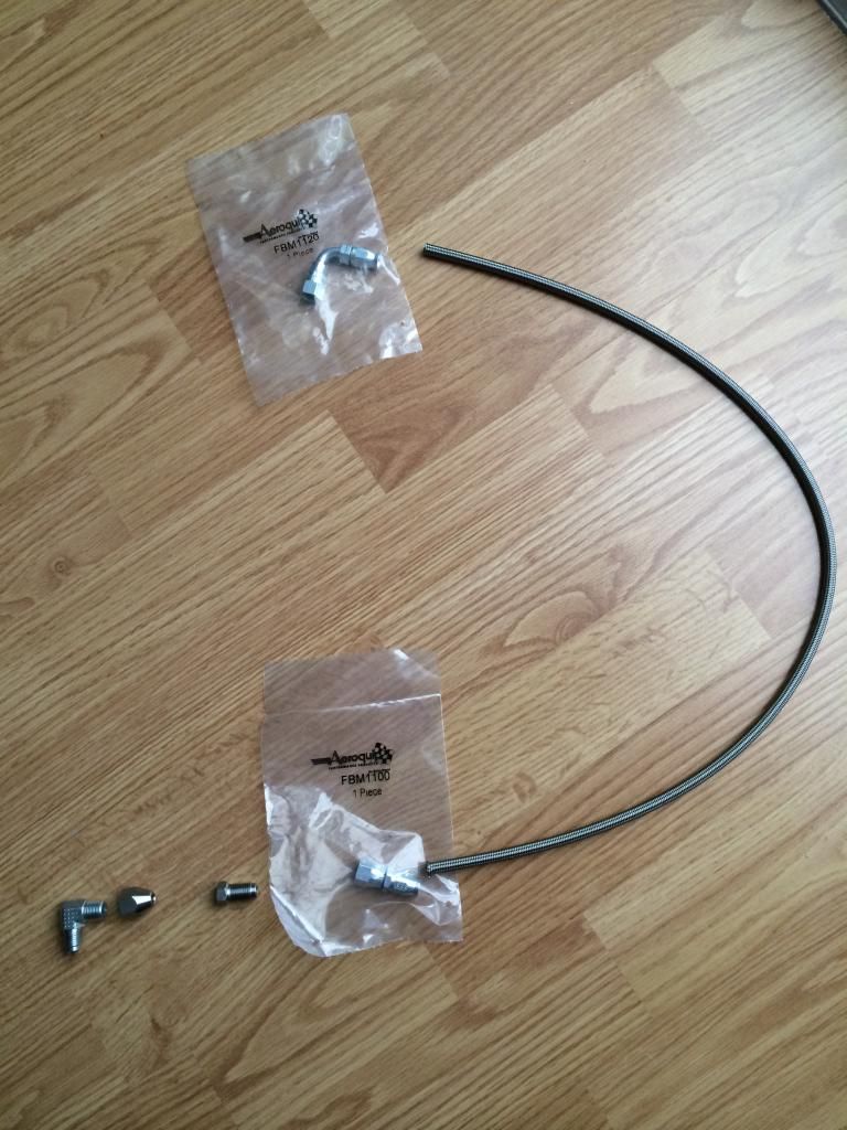 A mate who owns a car garage down the road will use his professional grade brake pipe flaring tool once I've got the rigid lines cut to length. I'll get a cheapy pipe bending tool off of eBay to put some light bends into each one, running from the front of the engine along the top of the exhaust valve cover. The flexi lines will then enter the top of the engine bay via holes in the tinware (there's already one in the left hand side), where the sensors will then mount at the back. The rigid lines will be 450mm long, the flexi lines will then be 600mm long; the AEM kit uses -4AN fittings, as their sensor has this male thread; mine are -3AN; the smaller diameter should help reduce any accuracy lag in that section of pipe versus the manifold. In terms of taking a feed from the manifold, I've been able to re-utilise the erroneously fitted 2 x Lambda bosses. The original plan was to run 2 x Lambda probes immediately before the secondaries enter the turbo flange, but we decided not to do this (instead mounting a single Lambda between turbo exit and silencer input). The 2 x "wrong" Lambda bosses were going to remain plugged with screw-in bungs - which irritated the hell out of me, being Mr OCD - but now I'll use some new hex head bungs, drill and tap as 1/8" NPT and use them for EBP. 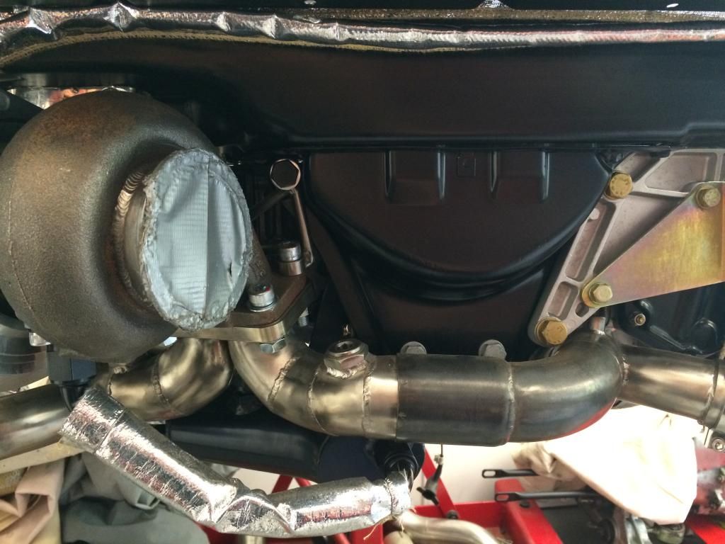 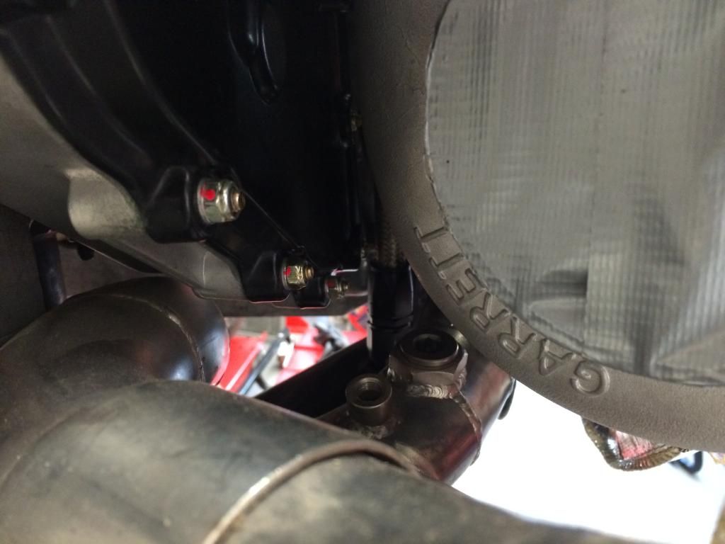 The left hand one runs very close to the turbos compressor housing, so have got a 45deg fitting to try and clear it. The electrical feeds for both sensors have now also been incorporated into the engine wiring loom....time to crack on and make these couplings and get the sensors mounted. |
||
|
07-19-2014, 11:41 AM
|
|
|
Kartoffelkopf
|
Exhaust Gas Temperature
On another subject, a very quick purchase in order to expediate the wiring loom manufacturing; I confess to not having pulled my finger out to research how we feed thermocouple sensor feeds into the ECU, before we needed to finalise the loom design.
The EGT sensors I'm using are fairly standard K-Type units, but there are complications with how you interface into them; only a mechanical connection (nut and bolt with ring terminals, or friction fitting using a pair of blade connections) is permissible. Soldering another lead onto the sensor is definitely a no-no, as the solder joint creates a cold junction in the circuit, therefore completely changing the temperature reading. Any wire that you use must also be suitable for K-Type thermocouples, ie., solid core....thus, not something you ever want to include into a loom like the one being made - solid core wires being a recipe for future headaches. Also, the heat transmission along the signal path to the ECU is something to be considered. So, an interfacing solution is needed. Some Googling revealed that AEM make a unit that both amplifies and cleans up (processes) the signal for up to 4 x thermocouple inputs. Some clever A/D conversion, signal processing and then I presume some D/A conversion back again gives a 0-5v analogue output which can then be used to feed an input into the ECU. RS-232 is also supplied, should anyone have the need to interface this way. 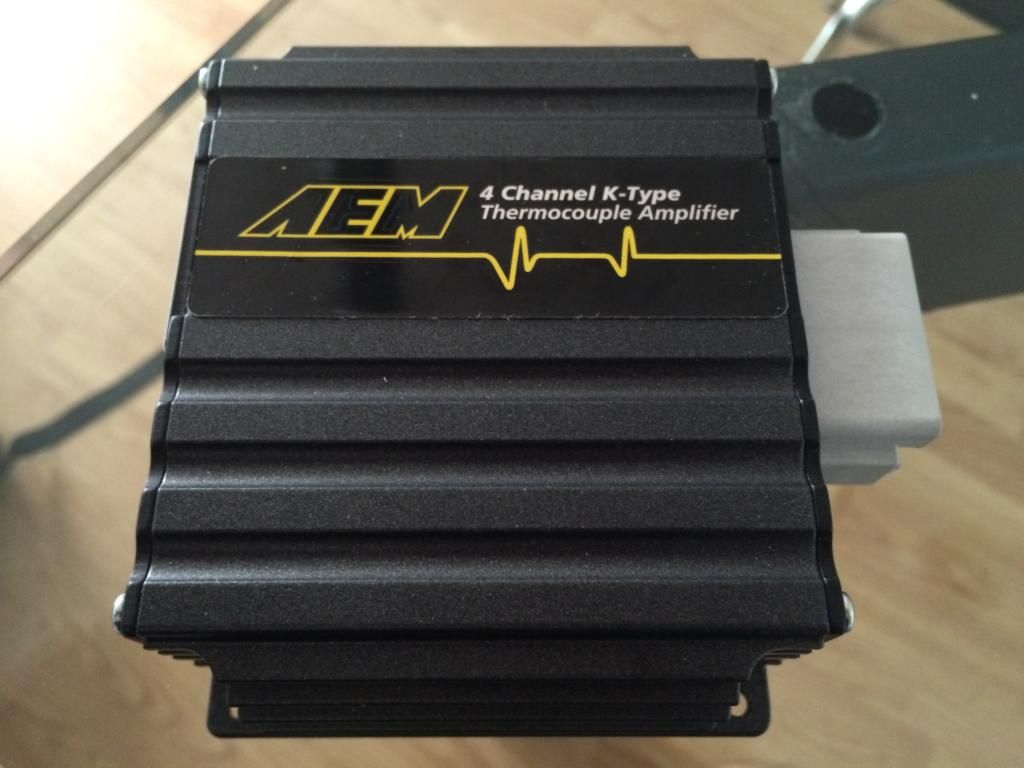 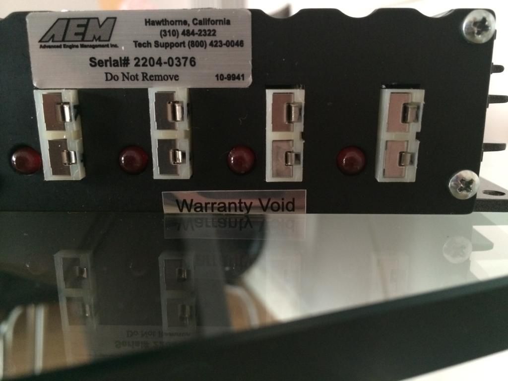 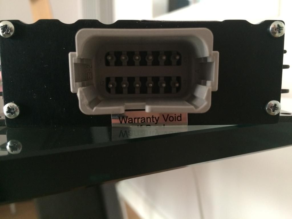 I had to move quickly with acquiring this unit, in order to get Simon @ Sileck (the racing wiring loom guy) to build in the power and signal feeds into the harness. Final drawings were almost completed, so was keen not to keep going back-and-forth with unclear requirements and constant changes...sure-fire way to p*** anyone off. The EGT thermocouples will run as a separate harness to the cabin, and not included in the main loom (per above reasoning). The AEM unit will sit alongside the MBE ECU under the passenger seat. Think it's safe to say that we've almost run out of sensor inputs to the ECU now! |
||
|
07-19-2014, 01:19 PM
|
|
|
Kartoffelkopf
|
In other news....
Had a little spending spree with tooling for the lathe. I'd been meaning to finish off the refurb project by doing a complete oil change (headstock and gearbox), also to get some soluble coolant and a DECENT SET OF CUTTING TOOLS!! So, an order was placed, and now have a very nice set of indexable carbide tipped (replaceable) tools. This was driven by the need to have a boring bar, so that I can make the plastic collars that set the coil-on-plug units into the valve covers. At the moment they are far too small, and rattle around the original holes. I've made the first collar, and it does the job perfectly! Apart from anything else, it's so nice to be using new tools, nice and sharp, accurate.....perfect. A 6mm boring bar has got the ID spot-on, so that only a quick squirt of duck oil is needed to push the CoP into it, then it grabs like a limpit. No wobbling on the O.D. to the valve cover either. The CoP is retained by means of the spark plug tip being removed, and the coils having a ratchet type mechanism that locks onto the spark plug thread......Five more to make for the top bank of plugs, but the lower bank are going to be held differently, as the newly machined holes in the valve cover are a lot smaller than the top banks, and oval. So, some RSR style "fingers" with plastidip ends will be made to hold these in place. 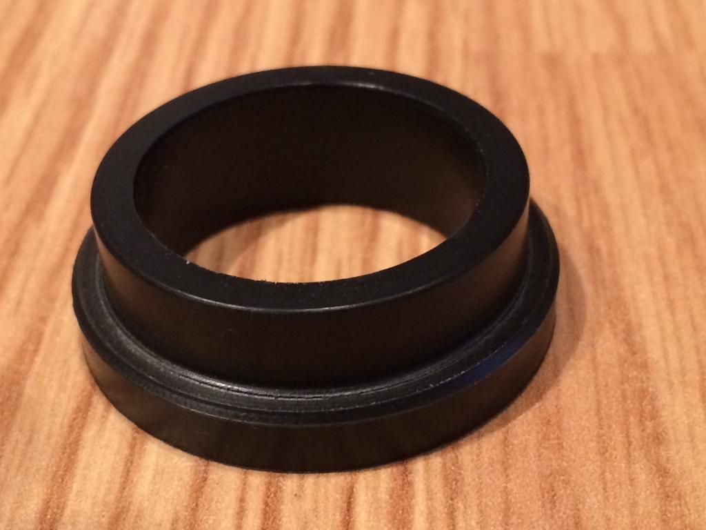 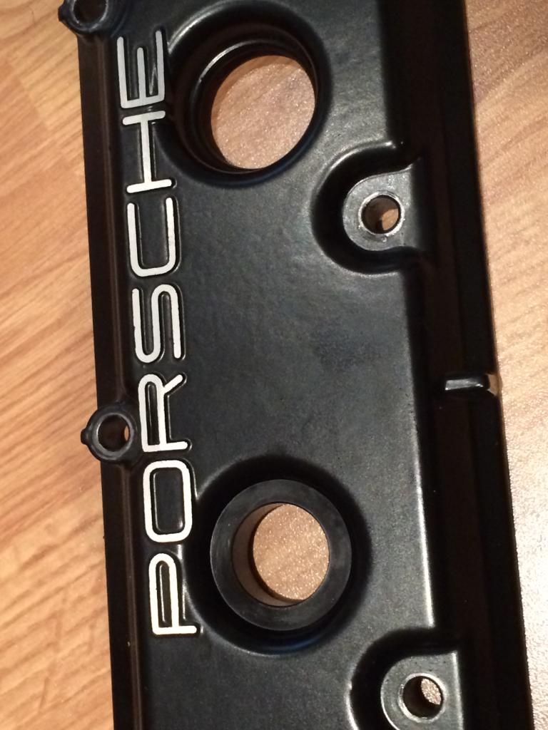 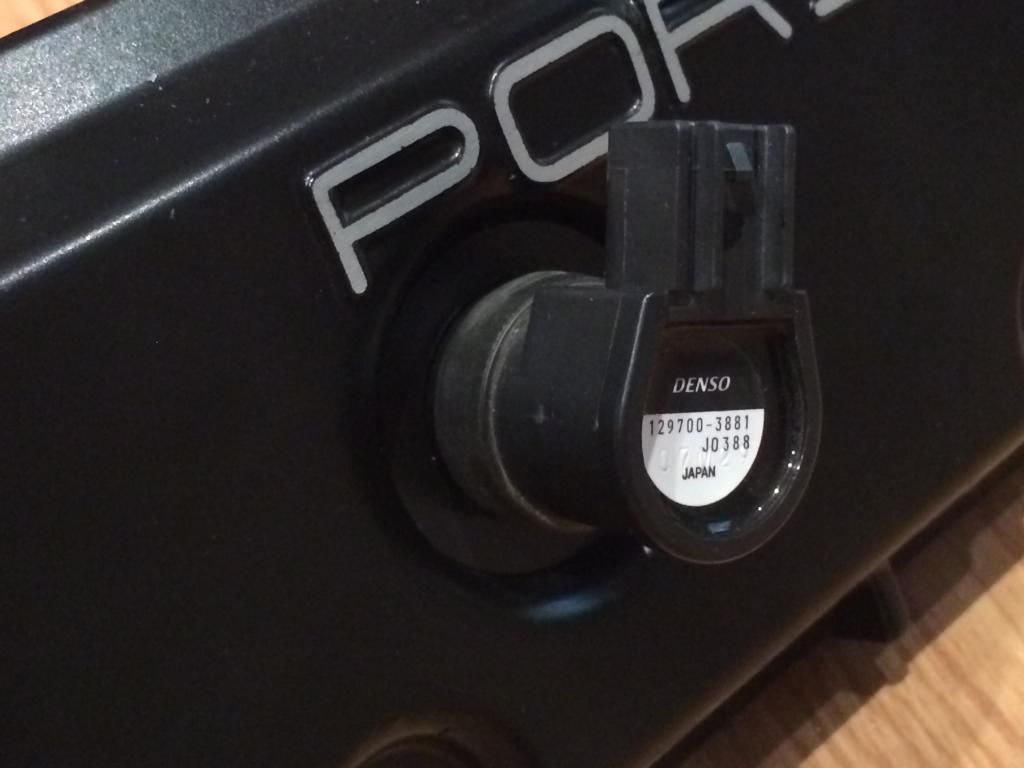 Right, back into the garage to finish cleaning the inside of the lathes headstock....oil looked fresh but I don't think it's been cleaned out since the day it was built. Far too much metal in there for my liking, so being very thorough with cleaning everything out before refilling. |
||
|
07-19-2014, 01:34 PM
|
|
|
Kartoffelkopf
|
Coil-on-Plug collars
A couple of very productive evenings, spending some "quality time" on the lathe to get the top bank of coil-on-plug collars made.
Four of them are easy; cylinders 2, 3, 4 & 5 are all the same, the CoP sitting fully in the valve cover in whole-holes. The #1 plug is pretty easy too, but because the valve cover has a semi-circular cut-out butting up against the timing chain housing, the depth of the smaller OD needed to be deeper; +2mm works nicely. 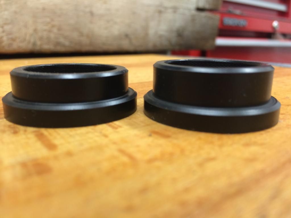 Number 6 is a different ballgame! This is where the semi-circular valve opening then butts up to the casting from the power steering pump assy, which appears "squashed"; its semi-circular shape not being concentric to the valve cover. --> 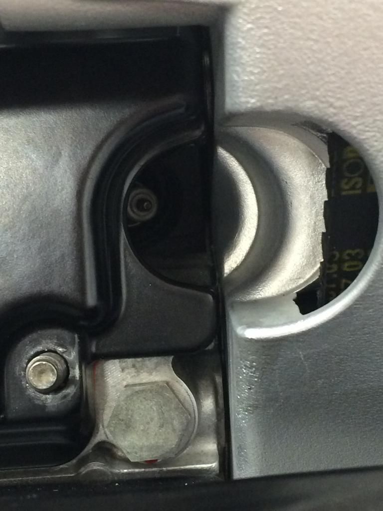 Now I'm glad I bought that 4-jaw chuck last year Mounting the bored material, with both OD's turned but not parted-off from the bar of stock material, I remounted it from the 3-jaw into the 4-jaw with a 4mm offset. Some careful machining later --> 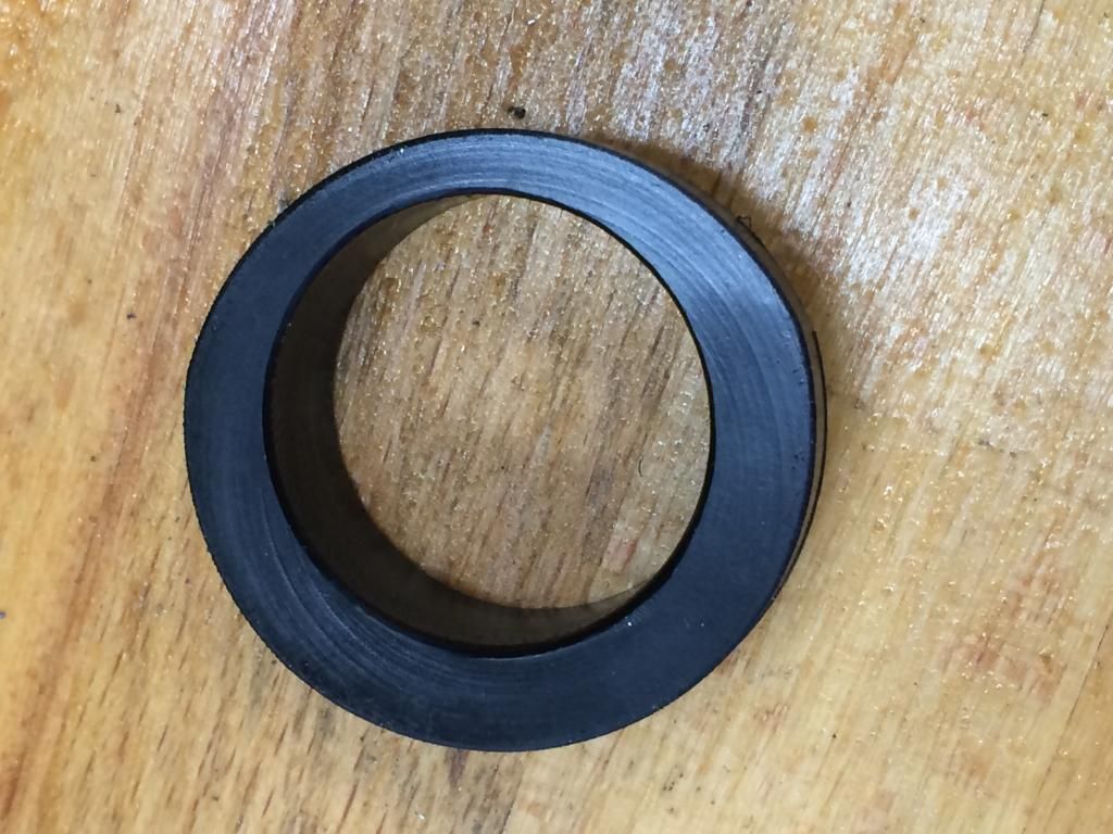 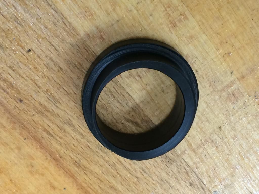 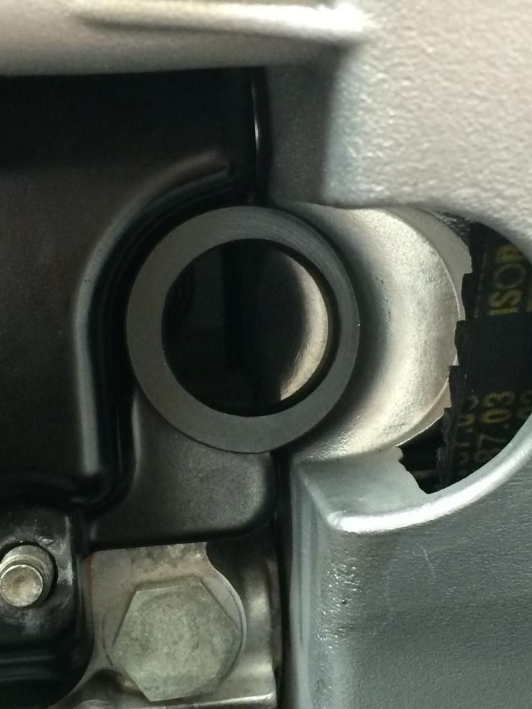 And now a set of 6 ready to go ---> 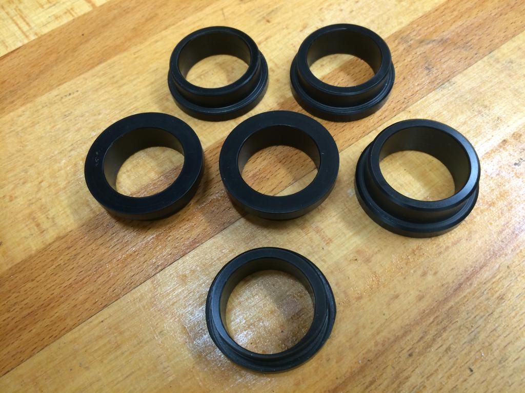 For the bottom bank of CoP's, per previous post, I was going to use RSR style stainless steel fingers to sit on top of the coils, but it was niggling me that all they were doing was preventing a unit from making its exit from the engine.....in reality not something to worry about, as the ratcheting mechanism on the coils is very strong. What the RSR fingers wouldn't stop is the CoP's wobbling about in the (albeit smaller) valve cover cutouts. So, with plenty of plastic stock left over, I've now designed some similar style collars for the bottom coils, but smaller in diameter; four will require 2x milling operations in order for them to fit inbetween the strengthening ribs on the cover. The other 2 should work as-is, without any machined flats on the larger of the OD's. Have made 3 collars so far....stay tuned, possibly more on this tomorrow night.
And that's about it for todays update....time for an early night; too loud to have the lathe going at this time in the evening! |
||
|
07-21-2014, 03:35 PM
|
|
|
Kartoffelkopf
|
Quick update time.....
Only had one day over the weekend to get a few odd jobs done, but quite productive nonetheless. All of the coil-on-plug collars are now finished, very pleased with the lower CoP collars that are a very nice snug fit inbetween the strengthening ribs of the valve covers; there's just enough squash in the rubber sleeves to allow the coils to engage the plugs at the correct angle - of course, they're not perpendicular to the heads. 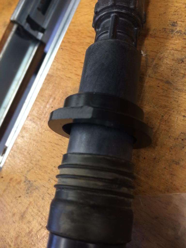 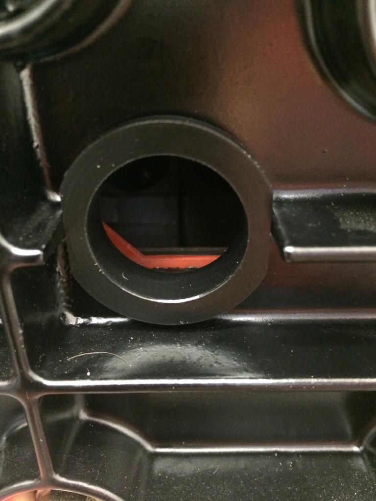 I also ordered some cutting fluid for the lathe the other week, some nice Supercut 4000 which is far less prone to bacteria build-up, non foaming and translucent, so a lot easier to see the work you're machining versus the cheaper milky solution. As a result, I've now prepped the 2x Lambda bungs (exhaust backpressure feeds), ready for when the 1/8" NPT tap arrives (hopefully tomorrow). These are 302 grade stainless, and I have to say, they machined beautifully....none of the shenanigans that you sometimes get with stainless: 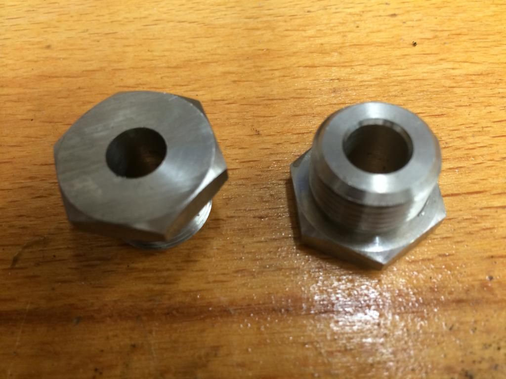 The fuel return hose mentioned previously, is now fitted onto the tank. A new tank filter also installed; was amazed to see how much detritus was captured at the base of the old filter! 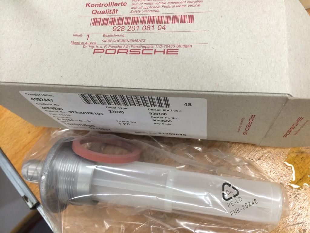 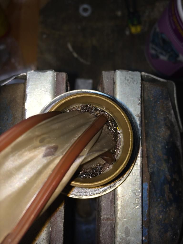 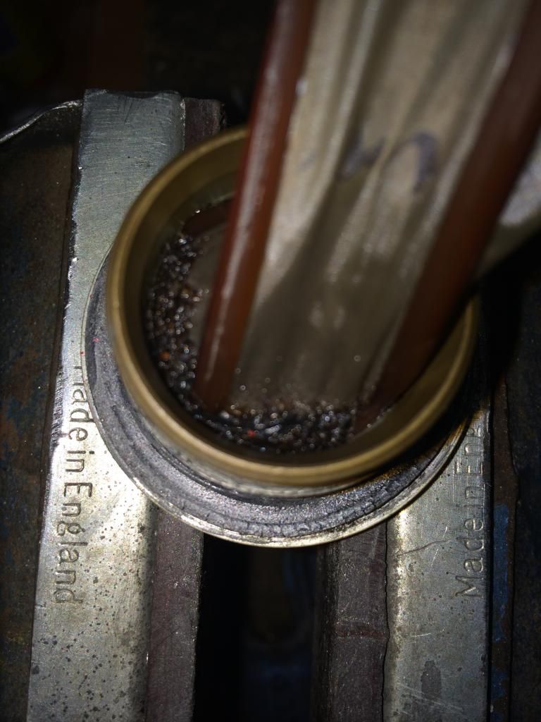 The exhaust backpressure sensor feed pipes are now made; 3/16" CDS stainless with stainless fittings, now flared with single and double flares, ready for hooking up to the flexi lines. Tomorrow lunchtime I'll nip out to collect the Laser pipe bender I've reserved at a local tool shop. If the NPT tap arrives in the post, then I can then get everything hooked-up and start routing the pipes around the sides of the engine. 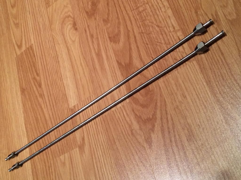 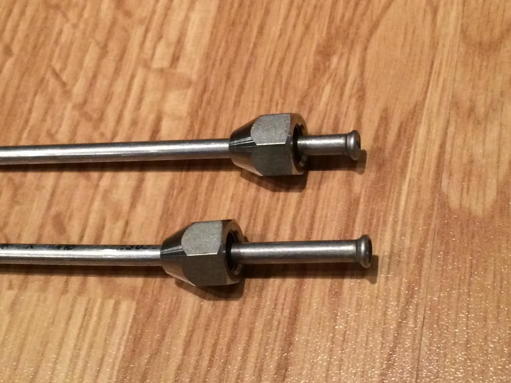 I also had a go at modifying the throttle linkage, trying to correct the position of the ball joint....not convinced I want to continue with my modification; feel like I'm short-cutting instead of making a new linkage, so may well make new spindles and plate...now that I've got new coolant and decent carbide tools. Bit annoyed by this part, it was "only" 4mm out, but it makes all the difference. Arriving in the next day or so should be my 3x Q-Max panel hole cutters and hand operated holepunch kit, so that I can get the holes cut into the tinware, for both mounting the Deutsch harness connectors, and running the lower CoP harness through to the bottom half of the engine. Once that's done, it'll need to be re-powder coated; apparently we may get away with just a quick dusting of powder, making it a lot quicker. Another boxful of parts delivered to the coating shop for a fresh coat of satin black:
...so, quite a lot of stuff happening. The eagerly awaited wiring loom should start getting built in the next couple of days, as the last 2x Deutsch conncetors have now arrived from Germany warehouse to the UK depot. Will keep you all posted. |
||
|
07-28-2014, 03:48 PM
|
|
 |
|
|
| Tags |
| 964 c4/c2/turbo , efi conversion , life racing , syvecs , turbokraft |


 1993 Porsche 911 (964) Turbo 3.3
 2006 Lotus Exige Cup 240 (#45 of 50)
 BMW M2 Competition
 BMW R1250 GS Rallye HP
 Ducati 748R


