|
|
|
|
|
| Author |
|
|
Registered
|
Engine Harness / Multi-pin Connector for Carb Conversion '83 SC
Folks,
I've decided to give it a DIY go and make an engine harness for my PMO conversion (although it is quite tempting to have Pelican Timmy2 - Dennis build me a harness): Building SC and Mid Year Engine Harnesses I'm considering ditching the old 14 Pin connectors and substituting with a modern weather proof connector. Also, I haven't found a source for the female 14 pin connector and the male is ~ $50... Meanwhile, the number of alternative multi-pin connector options are mind-boggling... I've kind of narrowed in on this one (understand I will require/have 8 of the 14 circuits remaining with the carb conversion):  8 POSITION MOUNT FLANGE M150L EXTERNAL 19429-0029 - 38452 Any thoughts or considerations toward going this route? Thanks, Gordo Edit - rats... meant to post on the Tech Forum.
__________________
Don "Gordo" Gordon '83 911SC Targa Last edited by Gordo2; 05-23-2014 at 08:18 PM.. |
||
 05-23-2014, 08:02 PM
|
|
|
Registered
|
You need to look closely at the pin size as it relates to current capacity and wire size. I have 1 Weather Pack 22 pin bulkhead connector and 2 Deutsch 12 pin bulkhead connectors and still used the original 14 pin connector. Of all of the connector types I have used and have in the car, I found the Metri-Pack or GT series to be the most flexible and easiest to use.
__________________
Steve Sapere aude 1983 3.4L 911SC turbo. Sold Last edited by sjf911; 05-23-2014 at 08:39 PM.. |
||
|
05-23-2014, 08:34 PM
|
|
|
ROW '78 911 Targa
|
Engine Harness / Multi-pin Connector for Carb Conversion '83 SC
PM me and I will give you the part numbers for the female 14 pin connector. Top, bottom and the pins.
All available from Porsche for about $30 total. Or, I could build you a carb style harness this weekend and you would have it next week!  Sent from my iPhone using Tapatalk
__________________
Dennis Euro 1978 SC Targa, SSI's, Dansk 2/1, PMO ITBs, Electric A/C Need a New Wiring Harness? PM or e-mail me. Search for "harnesses" in the classifieds. Last edited by timmy2; 05-25-2014 at 06:59 AM.. |
||
|
05-25-2014, 01:24 AM
|
|
|
Registered
|
Thanks Dennis
Quote:
 ? He's been giving me all sorts of greif telling me to get it on the road already... ? He's been giving me all sorts of greif telling me to get it on the road already... Without a doubt, the more I look into it - the more I appreciate & respect the high quality harnesses you make. Meanwhile, I've warmed to the idea of making my own engine harness for the following reasons: - In concept, the harness should be relatively simple since I've gone to carbs and removed nearly all of the ancillary electrical components / circuits. In concept... execution is proving otherwise as I am a research junkie... - I'm looking at mounting the connection toward the front of the engine (near the location where the CIS connector mounts) as opposed to the standard driver's side location. I like this idea from the standpoint that it will reduce the visibility of the harness (i.e. I like the idea / look of a "naked" engine). Somewhat of a non-standard harness approach. - I have a few items that I may decide to integrate into the harness as I dig into them (XDi ignition, Wideband sensor wiring etc.). As such, thus far I can't quite put my finger on what I want. - The OEM 14 pin connector design seems outdated (along with the rest of the car's wiring in general...), hence my consideration toward the Molex or other connectors. - I like the idea that taking on the harness will give me a better understanding of everything that connects to the engine. Greatly appreciate the offer, will take you up on the 14 Pin connector source (PM sent) as a back up in case my search for an alternative doesn't pan out. Gordo
__________________
Don "Gordo" Gordon '83 911SC Targa |
||
|
05-25-2014, 08:09 PM
|
|
|
ROW '78 911 Targa
|
Meant to post this earlier, don't know where it went???
14 pin cover 99965243040 14 pin base 99965243640 Female pins 99965237612 Cover and base part numbers may be swapped, but you need both anyways. PM replied to. No, your brother didn't call me!
__________________
Dennis Euro 1978 SC Targa, SSI's, Dansk 2/1, PMO ITBs, Electric A/C Need a New Wiring Harness? PM or e-mail me. Search for "harnesses" in the classifieds. |
||
|
05-25-2014, 11:02 PM
|
|
|
Registered
|
I'm All In
Too many options...
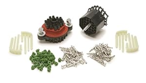
Now considering integrating the Electromotive magnetic pick-up and coil pack wire harnesses and remaining circuits into a single, circular multi-pin connector like this:  This config would provide a clean, solid single connection for the all engine related components. Meanwhile I'm debating the drawback of having everything harnessed together from a future troubleshooting perspective: - Having a stand alone wiring harness for the Electromotive components, zip tied to a second harness containing the required engine sensors/controls (oil press, temp etc) As I debate options - I went all in and started to unfurl the chassis harness.  No matter what approach I finally decide upon, I plan to separate power wires (like the large / 12ga yellow starter relay) to their own connector. Gordo
__________________
Don "Gordo" Gordon '83 911SC Targa Last edited by Gordo2; 05-28-2014 at 09:12 PM.. |
||
|
05-28-2014, 08:33 PM
|
|

|
|
Registered
Join Date: May 2004
Location: Boulder, Colorado
Posts: 7,275
|
I'd say weatherproofing is not really necessary. The 14 pin connectors don't generally go bad, and they aren't other than being up away from tire splash.
I assume you are going with Electromotive ignition? With carbs, I ran the oil pressure, oil temperature, idiot light, and the alternator warning light wires, along with positive and ground for two EGT probes to a 6 pin white plastic Molex mounted on the shock cross member. Its connector mate from the engine plugged into it. Molex is easy to work with, as you can crimp (and solder) the wires directly to the connectors, and then push them into place. Your first picture looks like a nice option, easy to mount, if it assembles in this way. The spiffy round ones in a later picture raise the question of how wires attach - butt connectors to wires it comes with, soldering bare ends into small, in place holes, or something easier. But if you mount the Electromotive stuff on the chassis, you avoid all that. Just pull the plug wires and you are done with that part of it. Chances are you are going to pull the plugs as part of whatever you are doing with the engine out anyway. The starter relay wire you can run straight to the starter, no connector needed beyond what it already has. When removing the transmission you have to pull the main cable off of this anyway, and to remove the engine you need to pull the alternator B+ off the starter, so nothing lost there. I bought an audio 4 pin, screw sleeve to hold the halves together, connector, and mounted it in a bracket on the left frame rail. It is indexed, and I cut the Electromotive sensor wire and soldered it into this connector. That way I can disconnect it quickly, and since I have the Electromotive stuff mounted on the chassis, I don't have to fuss with any of this when pulling or reinstalling the motor. Weatherpack is nice, but what you get in these systems isn't a connector which can be mounted, and it is a bit harder to pull apart than I would like for something I expected to have to do with some frequency (race motors are like that). So the result is I can pull the engine by separating one Molex, one crank sensor, and one or three wires at the starter. No backup light, and no speedometer, though. The backup light could easily have a spade connector somewhere down by where it resides, as you will be under there anyway come transmission removal time. And the speedo sensor is separate from the 14 pin harness anyway. Of course, fancy connectors have a cool look. I now have the full Electromotive system, with more sensor wires and two wires to every injector. I kind of solved the problems of having to unplug so much stuff by unbolting the throttle bodies from the manifolds (those nuts are pretty easy to get at), and leaving all that plugged in and in place hanging there when the engine is lowered out from under it. Instead of a transmission ground strap, and especially if you have solid motor mounts, consider making up a ground wire to run from one of the intake valve cover studs to one of the 8mm bolts holding the rear motor mounts in place. Easier to R&R, and harder to forget (especially when dropping the engine/tranny). Nary a problem with this. When cogitating on these things, keep in mind what will be where when the powertrain gets put back in. I replaced the entire wiring loom with, in most cases, smaller gauge Teflon coated wire (I happened to have quite a lot of that, with various codings). I thought it would be convenient and flexible to use those plastic connector blocks, where you insert a bare wire end and clamp it with a screw. Alas, I located that, and a couple of relays, in a place which seemed great with engine and tranny out. But once the need arose to get in there to do some trouble shooting, it was tough to get at. I should have mounted all that over to one side despite somewhat longer wire runs, to make it more accessible. Some thought, anyway. For all but the starter relay wire and the alternator to starter wire, just about any connector should have plenty of current carrying capacity. For the Electromotive, you surely will use a relay to connect directly (maybe via a fuse) from the starter main cable to the relay, so the relay coil connector doesn't have to be stout. Probably no heater blower going in? |
||
|
05-28-2014, 11:19 PM
|
|
|
83 911 Production Cab #10
|
If you are running Electromotive, they suggest to keep some of the wiring apart, like the Crank and Cam sensors so they don't get trigger by other signals.
I used the DME plug for the Unswitch 12 volts, Switch 12 volts and Fuel pump. (see Trog post # 60 of My PMO ITB Project) I went the other way, one loom per functions. Afer having some problem at the Main 35 pins connector, I decided to do a giant break box for the ECU so all circuit can be monitored live and isolated if required.  
__________________
Who Will Live... Will See  83 911 Production Cab #10, Slightly Modified: Unslanted, 3.2, PMO EFI, TECgt, CE 911 CAM Sync / Pulley / Wires, SSI, Dansk Sport 2/2, 17" Euromeister, CKO GT3 Seats, Going SOK Super Charger |
||
|
05-29-2014, 03:52 AM
|
|
|
Registered
|
Great Gouge
Walt,
Great info - really like the tip on the yellow starter relay wire. Seems like the best option and obvious approach, yet it never occurred to me. Also a great consideration on access to the connections once the engine/trans is installed - been thinking that one over as well. You are spot on for the engine config (PMO's,bare essentials, no heater blower etc.). Coil packs are mounted on top of the engine with a Clewett coil pack mount as opposed to chassis / firewall mounted. Engine config is posted here: Gordo's 3.2L Engine Rebuild - Ready to Reassemble I never considered the benefit of mounting the coils on the chassis (plug removal for ignition disconnect, DFU remains wired to XDi controller...) but wishing I had. At this point, I've taken that option off the table since I've purchased/installed the coils on the Clewett mount. I've only been looking at multi-pin connectors that use crimped pins/terminals (I'm not that good at soldering). I'm also primarily interested in mountable connectors (like the two I've posted). It appears that most multi-pin connectors can't be mounted without fabricating a specialized knock-out panel and I'm not up for that. Mainly interested in mounting for organization and cable stress / relief options, however I'm not completely opposed to zip tying connectors in the area ahead of the shock tower cross member if it provides an organized and efficient layout. --------------------------- JJ, You are out of hand - another option I would have never considered. Very nice work and configuration, but way beyond where I'm willing to go. Appreciate the point out to Trog's thread, I'll check it out. I hope to settle on an approach and buy the remaining wiring stuff this weekend. Thanks guys.
__________________
Don "Gordo" Gordon '83 911SC Targa |
||
|
05-29-2014, 07:41 PM
|
|
|
83 911 Production Cab #10
|
Quote:
Take your time. Last year, after installing the Electromotive kit, it was late in the summer but nothing is more satisfying then get her started on the first (or second) cranking. Bonne Chance JJ
__________________
Who Will Live... Will See 83 911 Production Cab #10, Slightly Modified: Unslanted, 3.2, PMO EFI, TECgt, CE 911 CAM Sync / Pulley / Wires, SSI, Dansk Sport 2/2, 17" Euromeister, CKO GT3 Seats, Going SOK Super Charger |
||
|
05-29-2014, 07:59 PM
|
|
|
Registered
|
Update and Pin-out plan
I went ahead and bought the Molex XRC 14 pin circular connector as previously pictured. Seems like a nice piece of gear.
Here's the plan for the pin-outs (Electromotive XDi Magnetic Crankshaft Sensor and DFU Coil wiring routed via Molex connector):  Let me know if you see anything whacky here - otherwise I'm moving out on it this weekend. Thanks, Gordo
__________________
Don "Gordo" Gordon '83 911SC Targa |
||
|
06-05-2014, 08:52 PM
|
|
|
Diving in 911
|
Timmy2 just sent me my new custom harness this week... all i can say is....... :-)
|
||
|
06-05-2014, 11:17 PM
|
|
|
83 911 Production Cab #10
|
Gordo,
You need to carry across the connector the DFU Shield (pin 16) all the way to the DFU. Inside every DFU cable, under the gray sleeve, there is a "one way" shield wrap around the wire and the shield wrap itself is wrap with a Bare wire. Its messy but on both side of your Molex connector you will need to get all 3 bare wires together and use 1 of your spare pin (M or N). On the DFU side, the shield stop there as close as possible to the connector (the shield is only connected to the ECU). 
__________________
Who Will Live... Will See 83 911 Production Cab #10, Slightly Modified: Unslanted, 3.2, PMO EFI, TECgt, CE 911 CAM Sync / Pulley / Wires, SSI, Dansk Sport 2/2, 17" Euromeister, CKO GT3 Seats, Going SOK Super Charger |
||
|
06-06-2014, 05:05 AM
|
|
|
Registered
|
Quote:
__________________
Steve Sapere aude 1983 3.4L 911SC turbo. Sold |
||
|
06-06-2014, 05:38 AM
|
|
|
Registered
|
Good Eye
Great Catch JJ,
Missed that one last night as I was focused DFU connector pin-out table, completely overlooking the drawings... Plan updated. Meanwhile, your point out made me look a bit harder at the shielded cable approach Electromotive is using. Based on the XDi instructions to extend wires using 16awg, with no mention of shielding - I'm assuming the shielding is really only needed in and around the engine coils and spark plug wires. I need to draw up the basic schematic as well, but it will include: I will be extending the DFU wires (via 16awg per instructions) to reach the controller under the passenger seat in the following manner: - Shorten the DFU shielded connector wires and insert in the Molex engine side connector - On the chassis side Molex connector I will run (4) 16awg wires (white, red, black and probably another black with 6" of the insulation stripped to ID) to the controlled to complete the DFU connection. Steve - I picked up the Molex connector from Mouser Electronics. At some point I will add the part #'s to the diagram - its quite a research project otherwise. Thanks again.
__________________
Don "Gordo" Gordon '83 911SC Targa Last edited by Gordo2; 06-06-2014 at 06:52 AM.. |
||
|
06-06-2014, 05:51 AM
|
|
|
83 911 Production Cab #10
|
Quote:
No connection throught the Molex, ECU side of the Molex grounded to pin 16 & DFU side of the Molex grounded. 
__________________
Who Will Live... Will See 83 911 Production Cab #10, Slightly Modified: Unslanted, 3.2, PMO EFI, TECgt, CE 911 CAM Sync / Pulley / Wires, SSI, Dansk Sport 2/2, 17" Euromeister, CKO GT3 Seats, Going SOK Super Charger |
||
|
06-06-2014, 07:43 AM
|
|
|
Straight shooter

|
I like this Painless Wiring bulkhead connector for building out engine harnesses:
 Item #40130
__________________
Of the value traps, the most widespread and pernicious is value rigidity. This is an inability to revalue what one sees because of commitment to previous values. In motorcycle maintenance, you MUST rediscover what you do as you go. Rigid values makes this impossible. ― Robert M. Pirsig, Zen and the Art of Motorcycle Maintenance: An Inquiry Into Values |
||
|
06-06-2014, 09:23 AM
|
|
|
Registered
|
Electromotive XDi Wire Harness - Carbs
Here's the wire configuration I went with for the XDi controller multi-pin connector:
 Some factory installed wires in the AMPSEAL 23 pin connector were not needed and were removed (MAP sensor etc), and the DFU extension wires were added. I wrapped the harness in Techflex F6 3/8" sleeving and put some heat shrink on the ends:  Gordo
__________________
Don "Gordo" Gordon '83 911SC Targa |
||
|
06-06-2014, 09:32 AM
|
|

|
|
Registered
|
Now that's disgustingly simple and uncluttered.

__________________
Steve Sapere aude 1983 3.4L 911SC turbo. Sold |
||
|
06-06-2014, 09:37 AM
|
|
|
Registered
|
Receptacle Mounted
Made a mount for the Molex pin connector receptacle (test fitment). Will be wiring it in today:
 Gordo
__________________
Don "Gordo" Gordon '83 911SC Targa |
||
|
06-07-2014, 06:57 AM
|
|
 |
| Thread Tools | |
| Rate This Thread | |
|
|


 1983 Porsche 911SC
 Heinz
Heinz
 Das Babe
 Das Babe Metalberiech
 Garage full of it
 P911
P911


