|
|
|
|
|
| Author |
|
|
Registered
Join Date: May 2005
Location: Houston
Posts: 5,488
|
Absolutely amazing and inspiring. The great pictures and your descriptions makes for an awesome thread.
Hopefully we meet-up soon. Curious..which 3D printer did you use?
__________________
Ole Skool - wouldn't have it any other way |
||
 11-24-2016, 03:38 PM
|
|
|
Registered
Join Date: Oct 2016
Posts: 260
|
Amazing job and engineering on this.
What are the advantages with itb? Sent from my iPhone using Tapatalk |
||
|
11-24-2016, 04:39 PM
|
|
|
Registered User
Join Date: Dec 2014
Posts: 989
|
1. They look so cool.
2. They sound so coool! 3. They improve throttle response. 4. They're just so coooool! |
||
|
11-24-2016, 05:05 PM
|
|
|
Registered
Join Date: Apr 2003
Location: Houston
Posts: 567
|
Quote:
Quote:
Quote:
Quote:
 Quote:
 Quote:
https://mag.levelxms.com/2014/08/01/benefits-of-individual-throttle-bodies/ But as Mick_D noted, they're cool! Here are a few more pictures of the whole setup       And here is a video of the "first start". This is before the ITBs were balanced and idle set https://youtu.be/CMFJ9AJPE_U And another once everything was adjusted https://youtu.be/nL2u4UGRrN4 Andrew from Rasant Products was a huge help getting it the AEM Infinity setup and tuned. I highly recommend his EFI kit. Al Kosmal has been a huge inspiration as well with the Triumph ITBs and his linkage and throttle body kit are a great affordable option. |
|||||||
|
11-24-2016, 05:37 PM
|
|
|
Registered User
Join Date: Dec 2014
Posts: 989
|
Clay, where'd you source the ITBS? Guess I better go back and re-read.
|
||
|
11-24-2016, 06:02 PM
|
|
|
Chain fence eating turbo
Join Date: Dec 2008
Location: Austin, TX
Posts: 9,210
|
I didn't attend.
Thanks for the crimper link! |
||
|
11-24-2016, 06:35 PM
|
|

|
|
Registered
Join Date: May 2005
Location: Houston
Posts: 5,488
|
Bravo Clay!!!
Disappointed I missed Treffen, I was invited by Rudy and unfortunately had other commitments that day.
__________________
Ole Skool - wouldn't have it any other way |
||
|
11-26-2016, 04:51 AM
|
|
|
Registered

Join Date: Sep 1999
Posts: 944
|
When somebody steps up with a system like this for our cars, EFI setups will become more popular. The hot rod V8 guys are always ahead of the curve.
Prices will come down and the labor to install one will as well. I'm a patient man having learned that pioneers are the ones with arrows in their backs.  SEMA 2016: Holley Takes The Wraps Off Of Self Tuning Fuel Injection 
__________________
R Gruppe #111 Early S Registry #235 res ipsa loquitur |
||
|
11-26-2016, 07:42 AM
|
|
|
911T '72
|
I got my manifolds from Clay the other day. They are very nice irl!
 Now I'm collecting all the parts and I hope to start this build in early spring.
__________________
Dennis Good drivers have dead flies on the side windows. (Walter Röhrl) |
||
|
11-30-2016, 03:01 AM
|
|
|
Registered
Join Date: Apr 2003
Location: Houston
Posts: 567
|
I had a question regarding my fuse/relay setup, here is a little more info.
I wired the relay's opposite what the Bussmann DIY noted, with the relays installed right side up. This means that i'm switching using a ground signal, rather than a power signal. DIY Bussmann RTMR Fuse Block, Part 4 – Wiring and Schematics | Bodenzord This is the back of my setup.  The two terminals on the bottom are bridged together and connected to the battery. This provides power to both the fuses and relays (86) The other fuse terminal or "out" is connected to the relay power terminal (30) The 87 terminal provides power to the accessories; ECU, fuel pump, injectors and coils. The 85 is wired to C1-47 of the AEM Infinity 6 ECU. This is the ECU ground switch. The ECU provides a ground to the relay and is the switch. This is used for all accessories, ECU power, coils and injectors. The 85 for the fuel pump is C1-41 of the AEM Infinity 6 ECU. The ECU provides a ground to the relay and is the switch to turn on the fuel pump. This is just what I did. It is not the only way to do it, or the best way. The best way is to buy Rasant's kit with the wiring done. I did not save any money doing it myself, I just choose to because I wanted to learn the system and understand the wiring better for myself. |
||
|
12-08-2016, 05:13 PM
|
|
|
Bit Meister
|
I've read elsewhere that the vacuum lines should be equal length. From the pictures, I think I see that yours are not. Is there an appreciable impact with the MAP sensor to make them equal length, or not?
BTW, this is one of the threads that inspired me to do similar. |
||
|
12-08-2016, 06:26 PM
|
|
|
Chain fence eating turbo
Join Date: Dec 2008
Location: Austin, TX
Posts: 9,210
|
Quote:
Meaning, equal lengths probably aren't 100% required, but I'd strive for it. |
||
|
12-08-2016, 08:05 PM
|
|

|
|
I would rather be driving

Join Date: Apr 2000
Location: Austin, TX
Posts: 9,108
|
Quote:
The only issue with ITBs is getting a quiet MAP signal at idle. The reversion pulses can easily be seen by the sensor at low intake gas speeds. Yes, these are the same reversion pulses that confuse the AFM in Motronic and Flapper in CIS. The difference is that you can ignore some of the noise and fluctuations in software and tuning. This is a great build. I would like to know more about where you had the manifolds cast and that process.
__________________
Jamie - I can explain it to you. But I can not understand it for you. 71 911T SWT - Sun and Fun Mobile 72 911T project car. "Minne" - A tangy version of tangerine #projectminne classicautowerks.com - EFI conversion parts and suspension setups. IG Classicautowerks |
||
|
12-08-2016, 08:13 PM
|
|
|
Max Sluiter
|
Quote:
__________________
1971 911S, 2.7RS spec MFI engine, suspension mods, lightened Suspension by Rebel Racing, Serviced by TLG Auto, Brakes by PMB Performance |
||
|
12-08-2016, 08:41 PM
|
|
|
Registered
Join Date: Apr 2003
Location: Houston
Posts: 567
|
I hadn't thought about the length of the vacuum lines affecting the map signal, but i'm not too worried about it. I'm getting a good responsive signal with this setup.
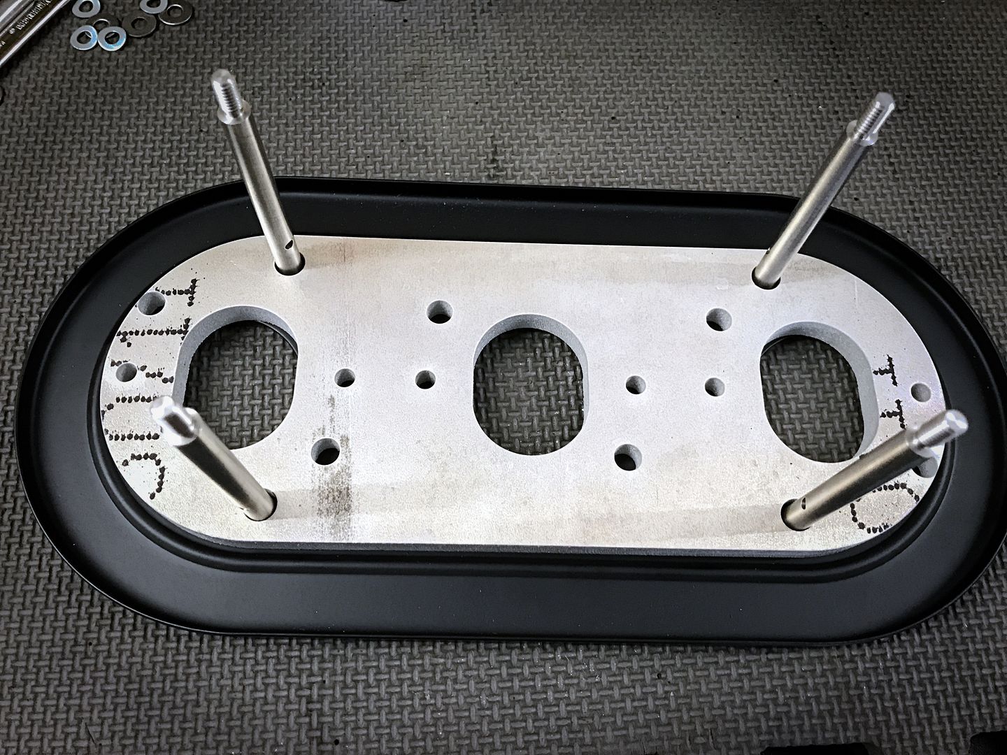
One issue I did experience was during WOT tuning. Several of the screens on top of the velocity stacks got sucked into the stacks. Luckily they were all stopped by the ITB butterfly.  I ran them for awhile without any filters, but I wasn't too comfortable with that setup for obvious reasons. I looked into filter socks, but read reports of issues of limited airflow with them. I settled on adapting a PMO Weber K&N filter and rain hat setup that I ordered from Pelican. The adapters started with more Triumph parts. These are intake boots that come on several Triumph motorcycles and a set of 3 can be had for about $15. These come with a round rubber coupler and clamp on one side, a bolted flange with o-ring on the other side. 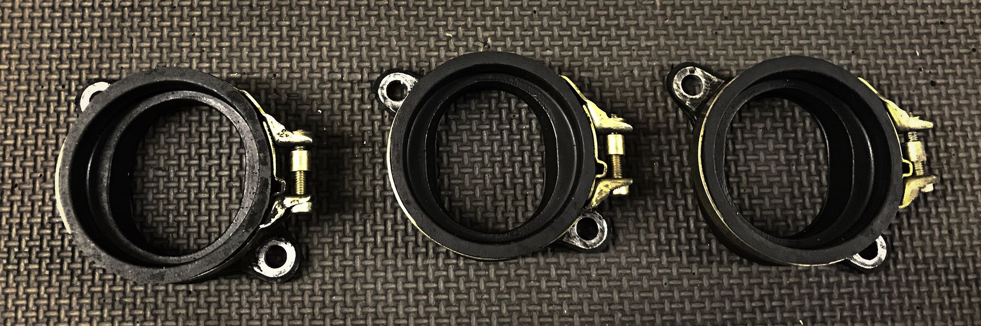 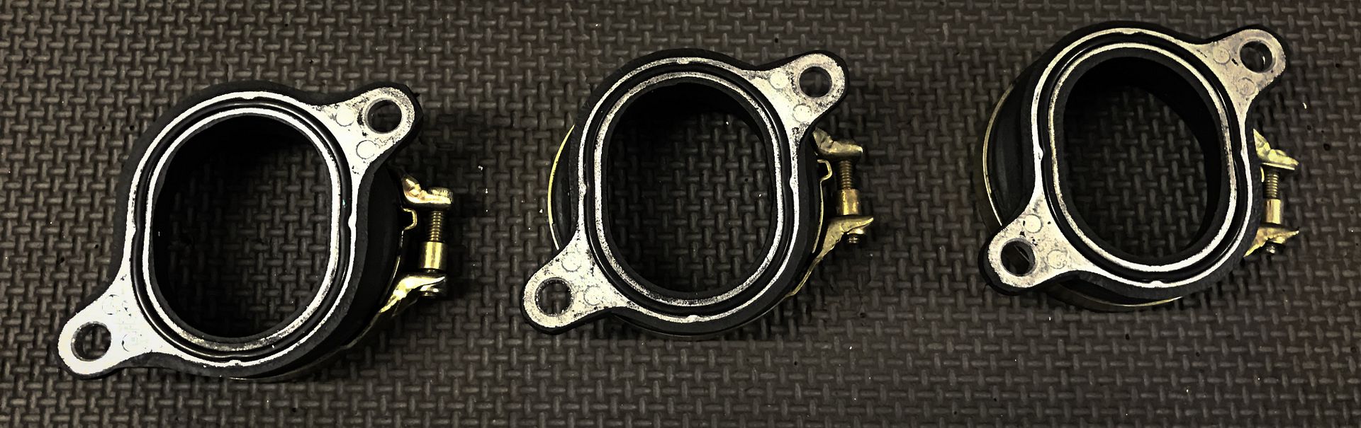 The coupler and clamp side fit on top of the ITBs, and I designed an adapter plate that was waterjet cut that the bolt flange side attaches to. 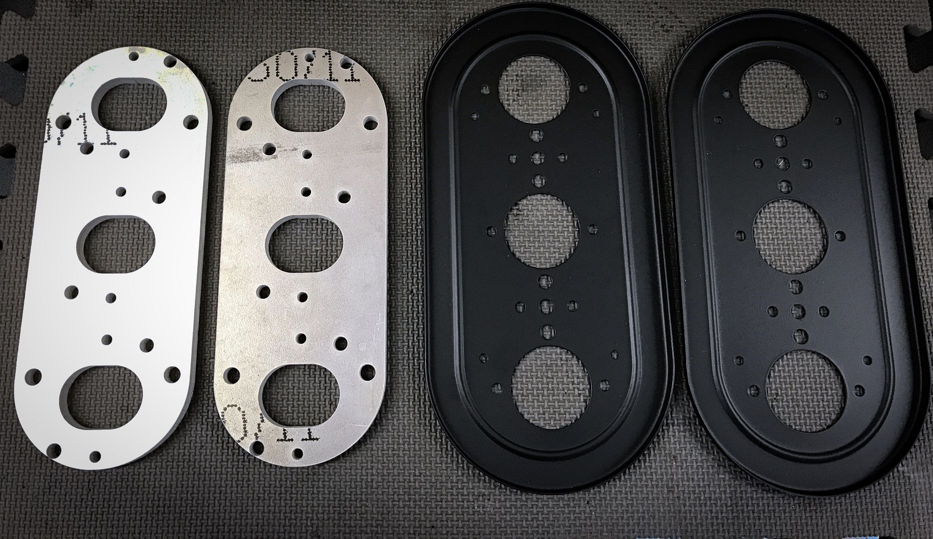 The plate is 3/8" thick to allow for clearance above the fuel rail 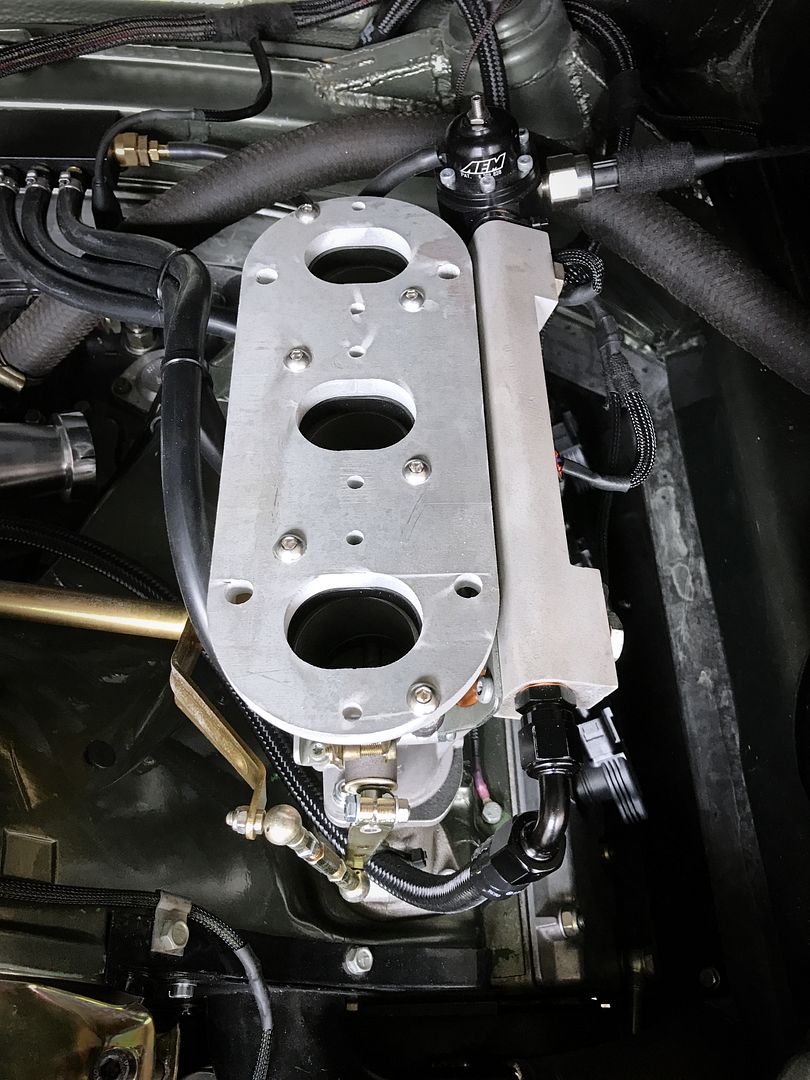 I previously had the FPR mounted directly to the fuel rail, but the new filter setup interfered, so I added a straight union to space it out. This is a better connection anyway. 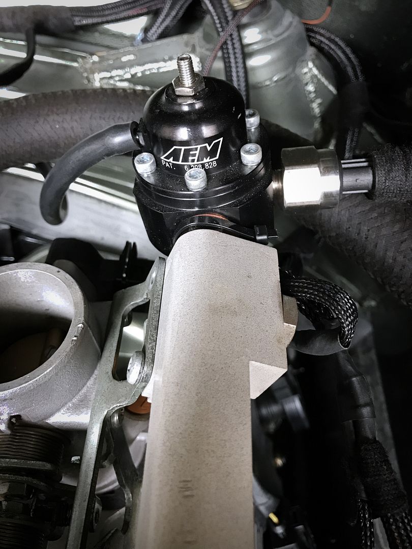 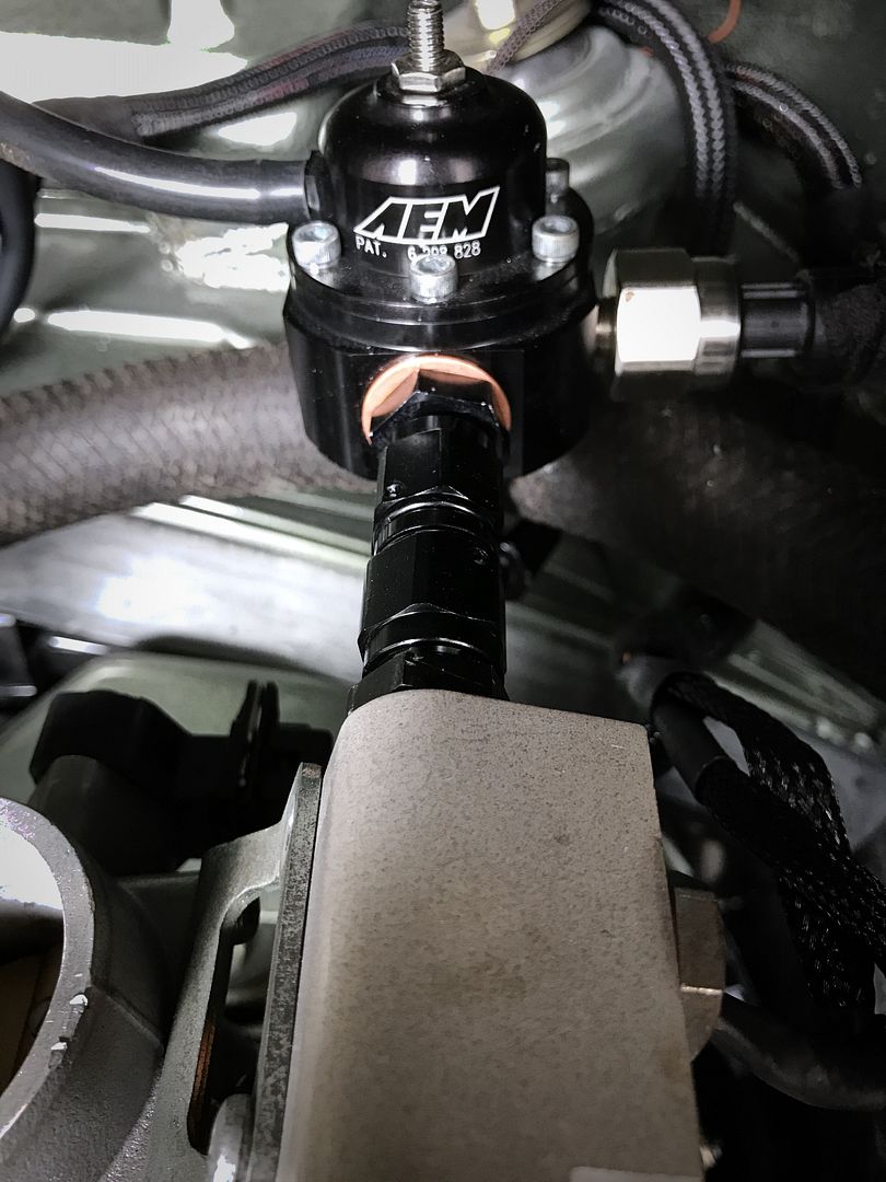 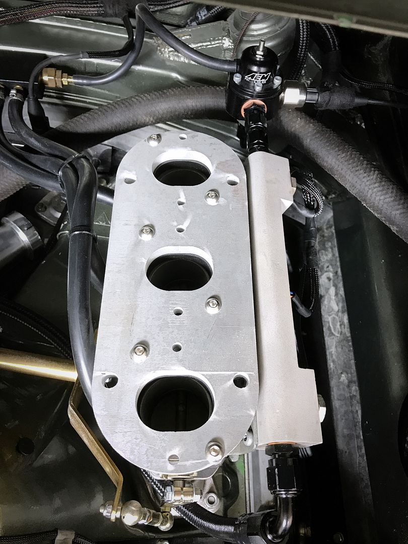
Last edited by Clay.0; 12-11-2016 at 11:57 AM.. |
||
|
12-11-2016, 11:25 AM
|
|
|
Registered
Join Date: Apr 2003
Location: Houston
Posts: 567
|
Next up was modifying the PMO filter base plate. Holes for the intake boots and velocity stacks were added by drilling through the holes in the plates
 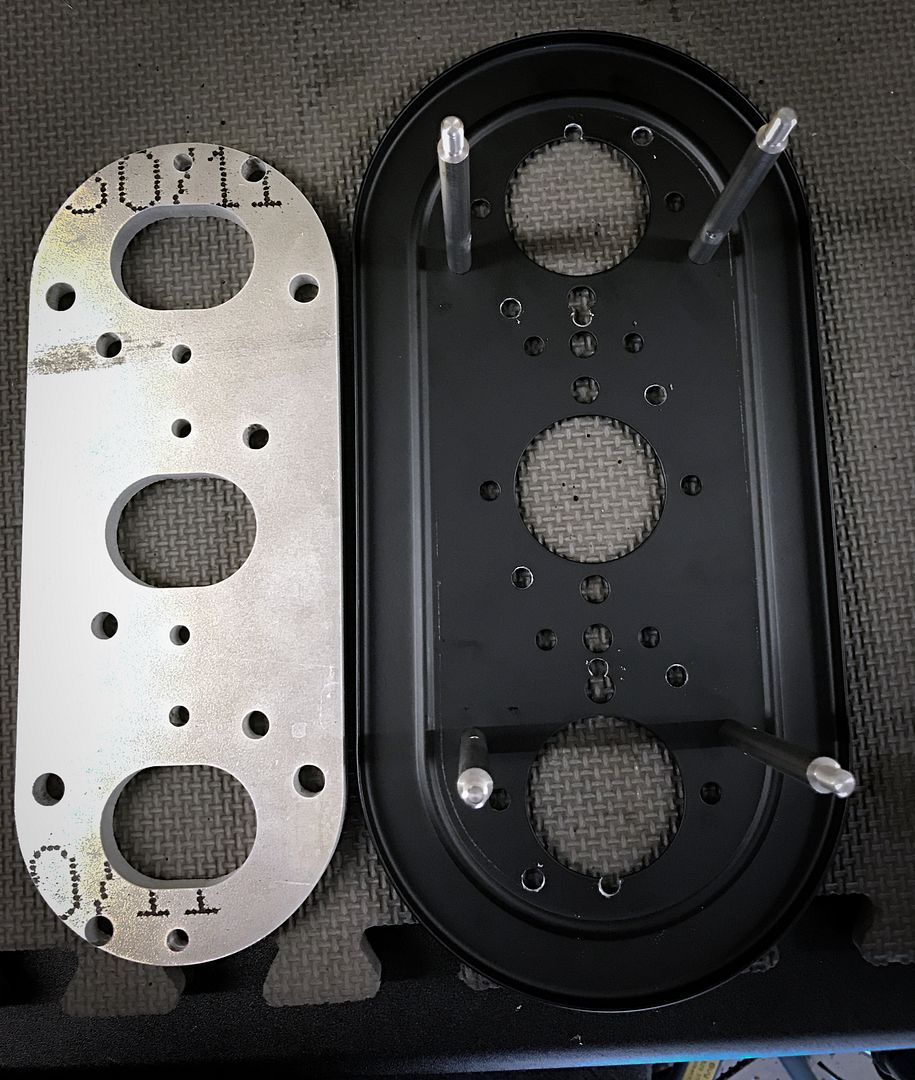 The Weber and Triumph spacing is off a bit, but it's close. The PMO base plate needed to be ground open a little with a Dremel. 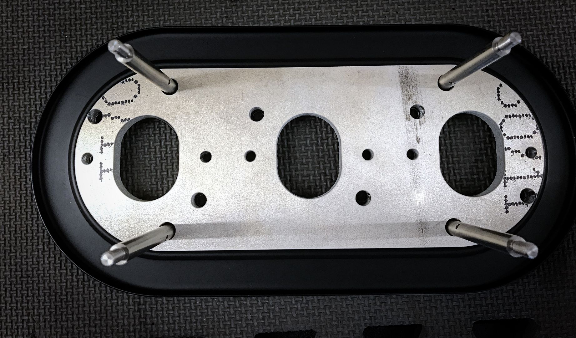 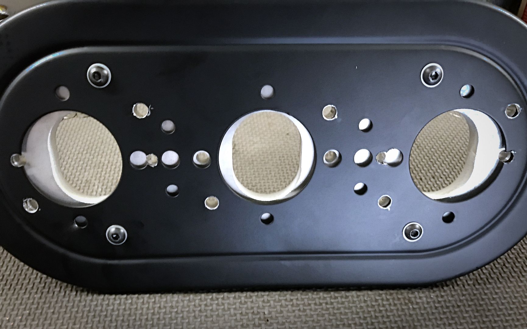 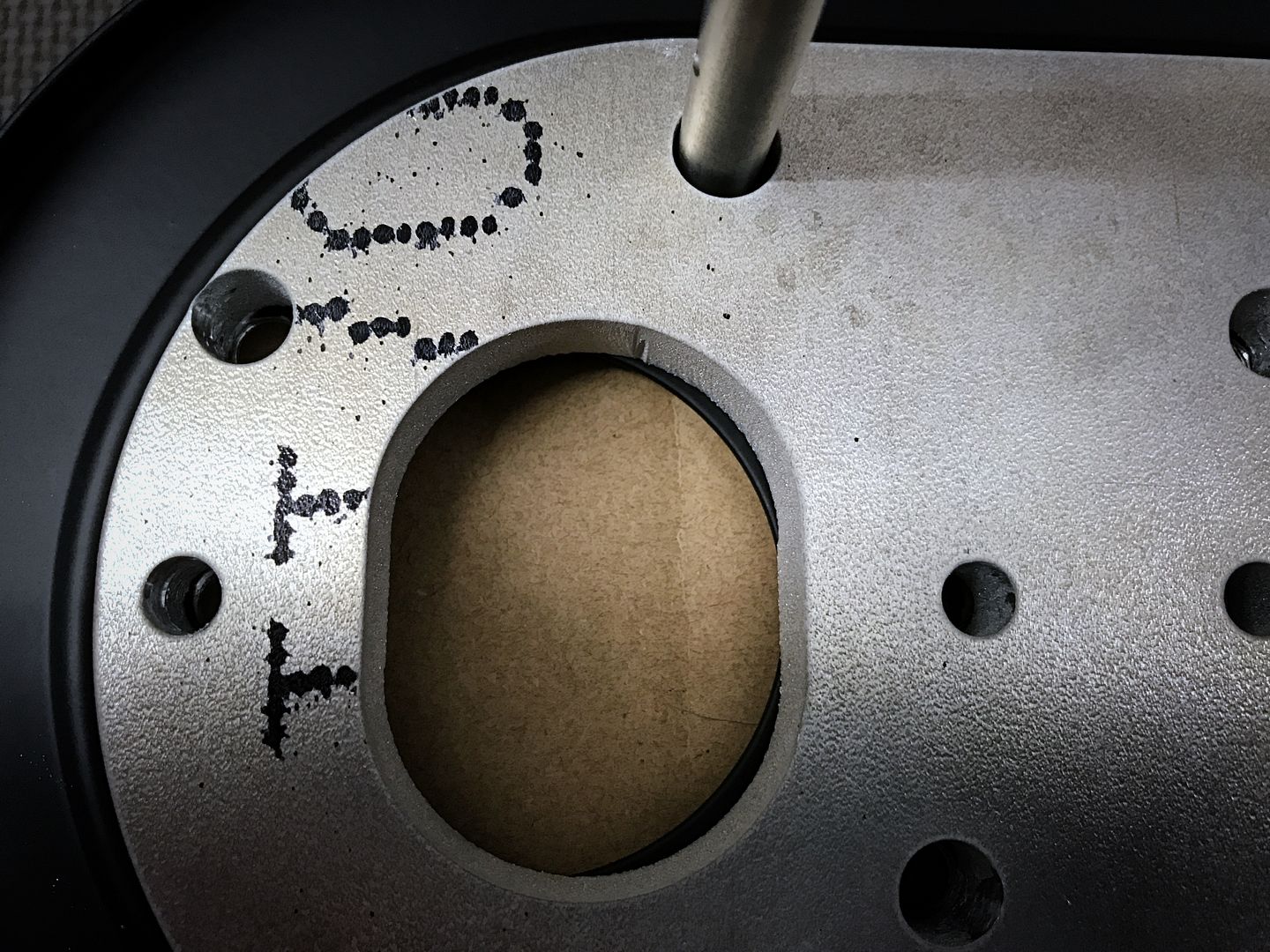 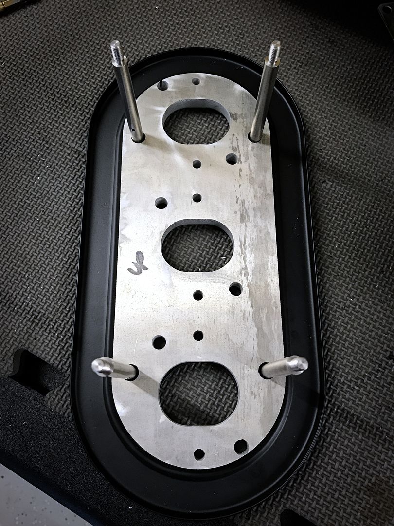 I designed the adapter plate off a old set of rain hats, apparently they used to use socket cap fasteners for the spacer rods, now they use button heads that are too big. So I swapped these out for button heads 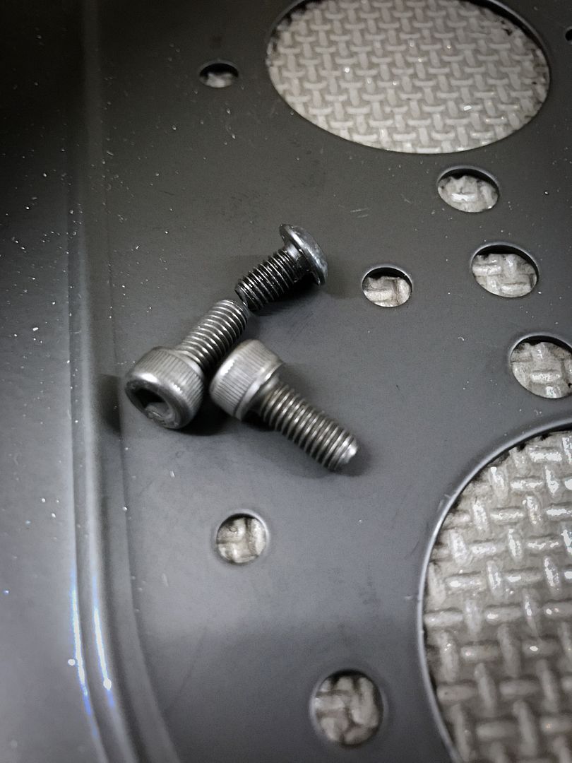
|
||
|
12-11-2016, 11:43 AM
|
|
|
Registered
Join Date: Apr 2003
Location: Houston
Posts: 567
|
Then assembly of the unit.
The heads of the hardware is on the top side so there's no chance of a loose nut making it's way into the ITB. 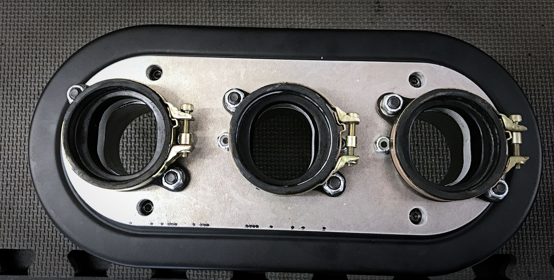 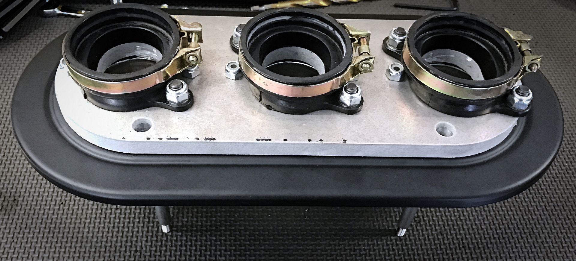 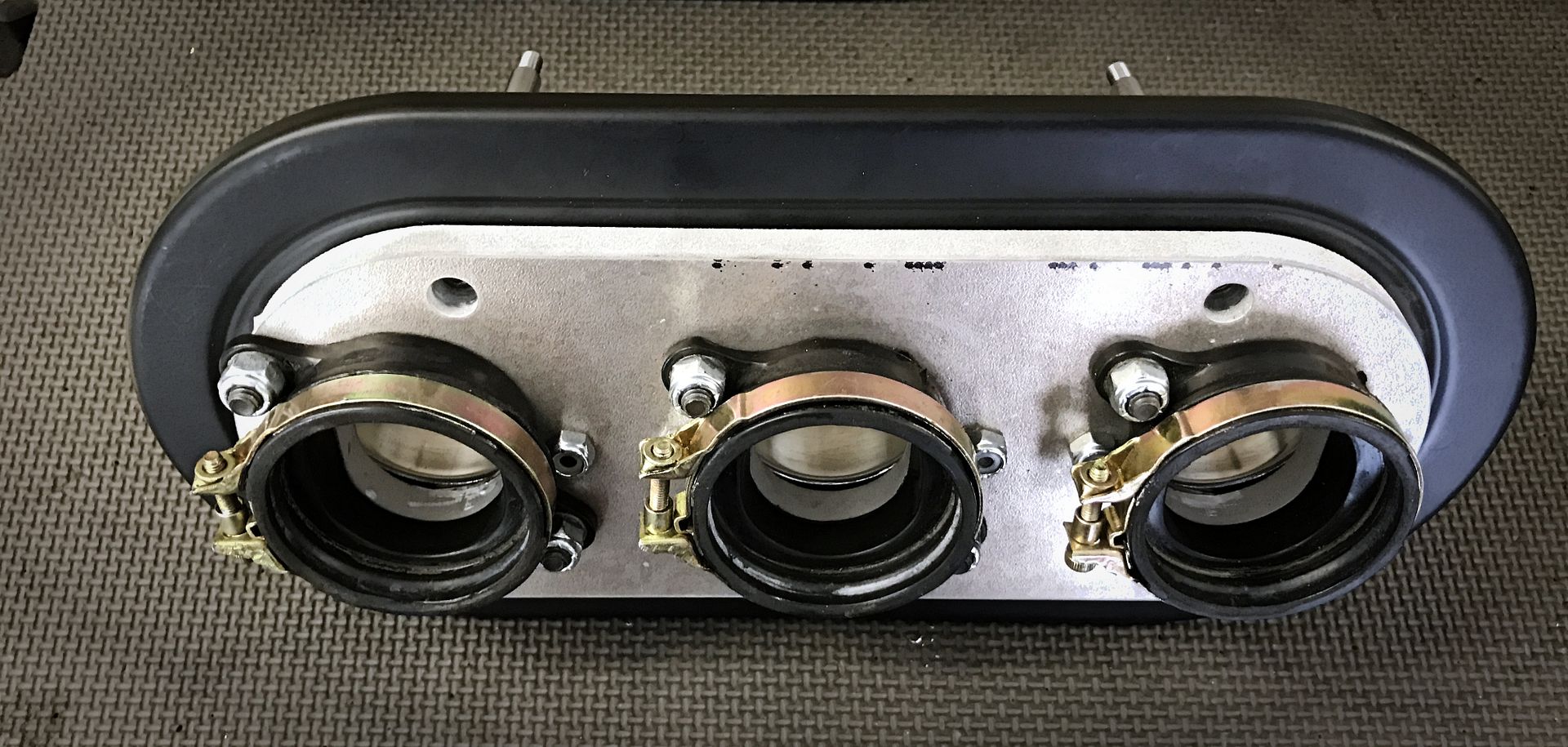 I used standard Weber/EMPI velocity stacks 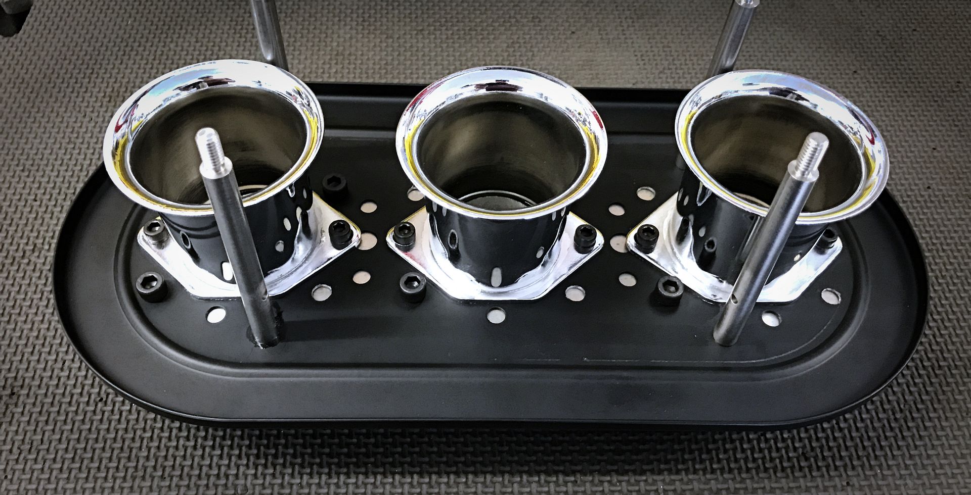 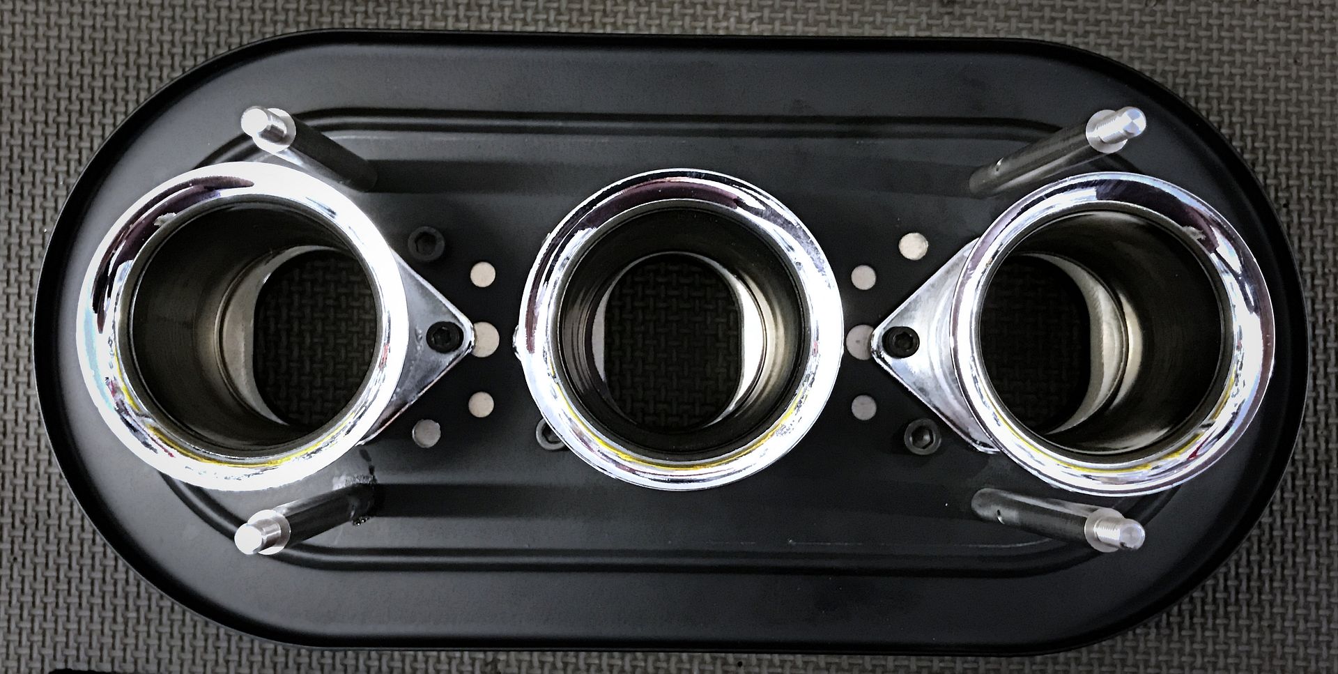 Standard K&N filter 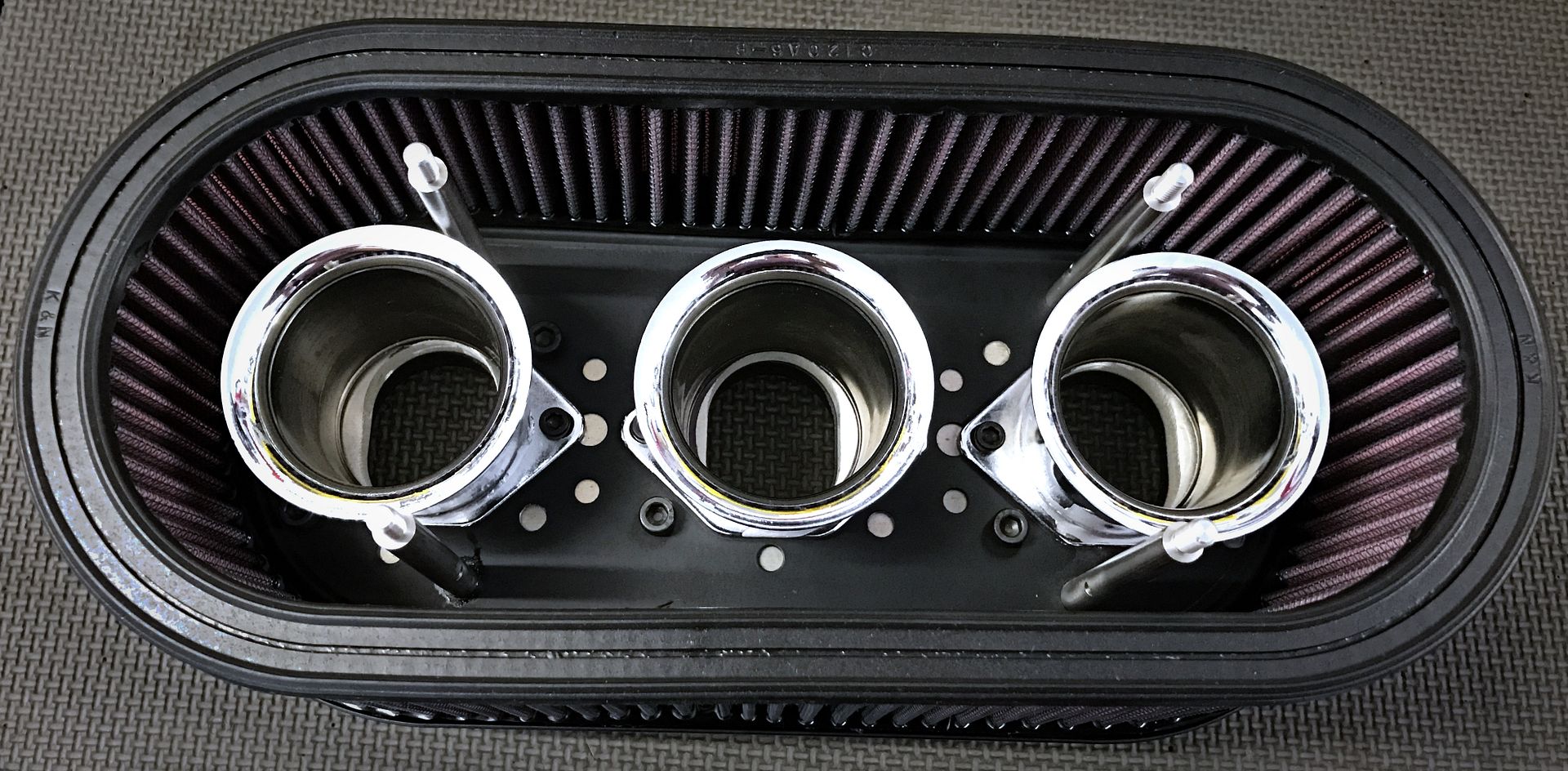
|
||
|
12-11-2016, 11:47 AM
|
|
|
Registered
Join Date: Apr 2003
Location: Houston
Posts: 567
|
Installation:
The way I had Al's linkage setup before was raising up to high and hit the adapter plate. Everything was shortened down and adjusted to swing lower. This ended up allowing the movement of the linkage to be much smoother than before. ITB linkage starting parallel to the throttle body 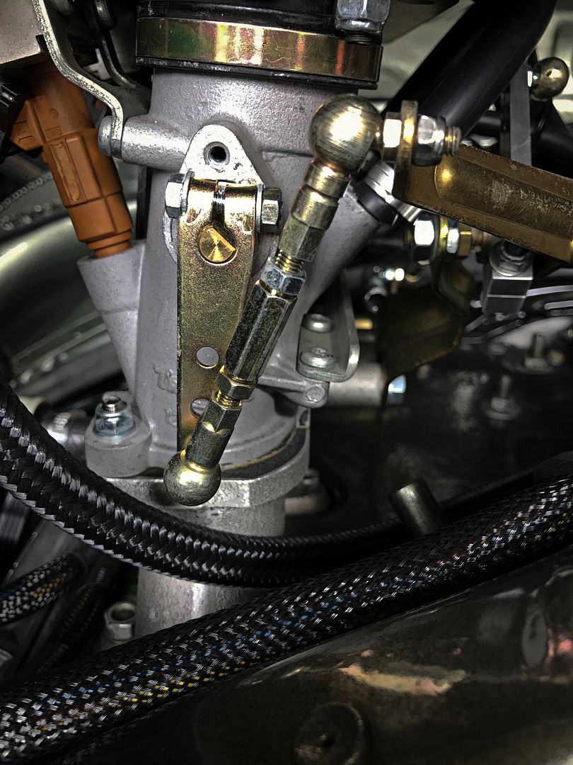 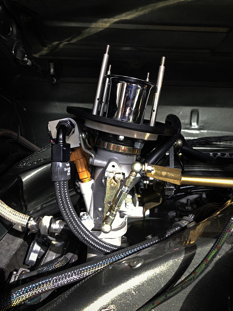 The aluminum pull linkage was also shortened 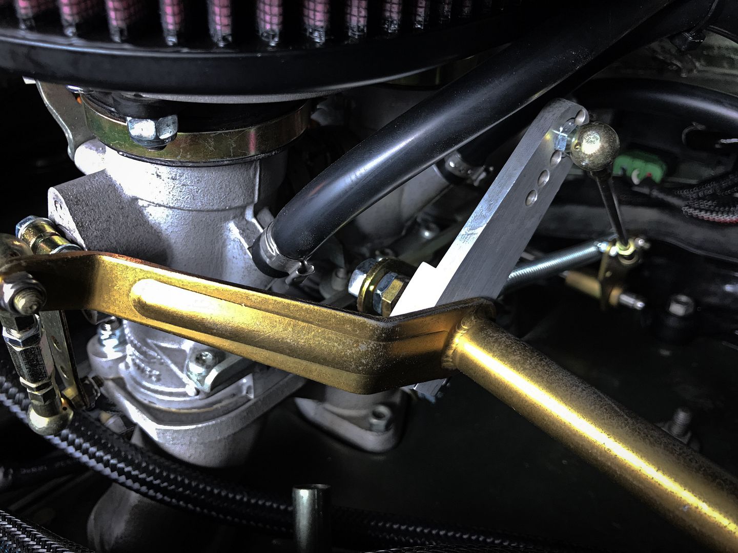 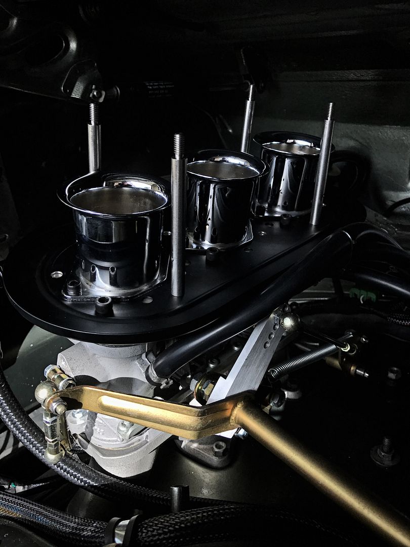 Now at WOT the linkage barely touches the filter setup 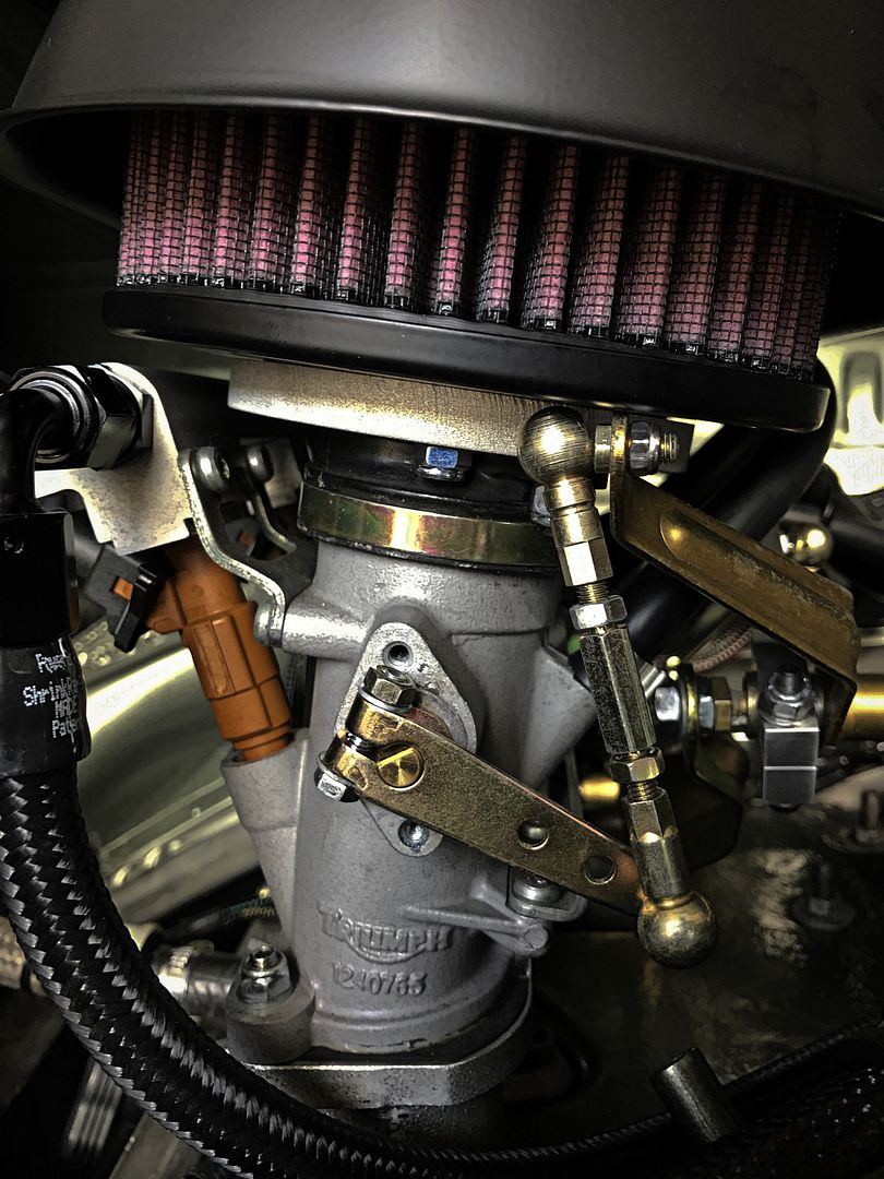 The assembly is connected to the ITBs with the allen hose clamps that come with the intake boots 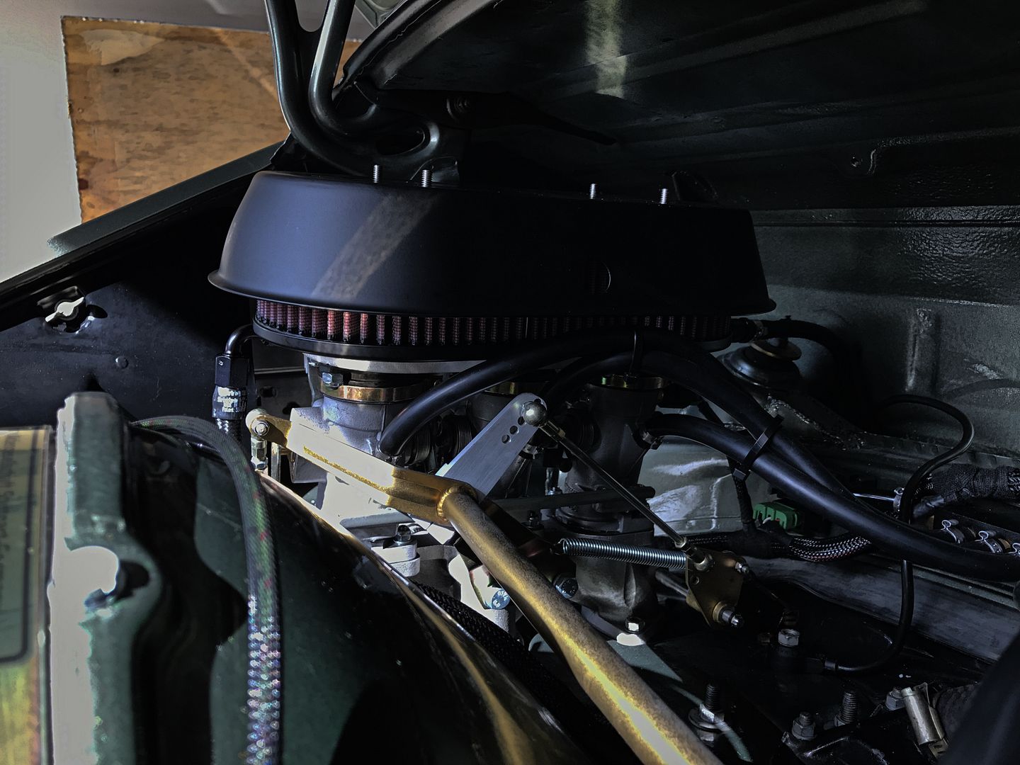 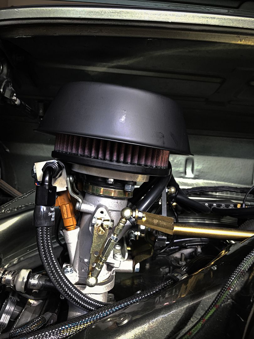
Last edited by Clay.0; 12-11-2016 at 11:55 AM.. |
||
|
12-11-2016, 11:51 AM
|
|
|
Registered
Join Date: Apr 2003
Location: Houston
Posts: 567
|
I messed with the adapter plates a little more
Using a 3/8" round over bit in my router, I opened up the ovals of the plate to better align with the velocity stacks 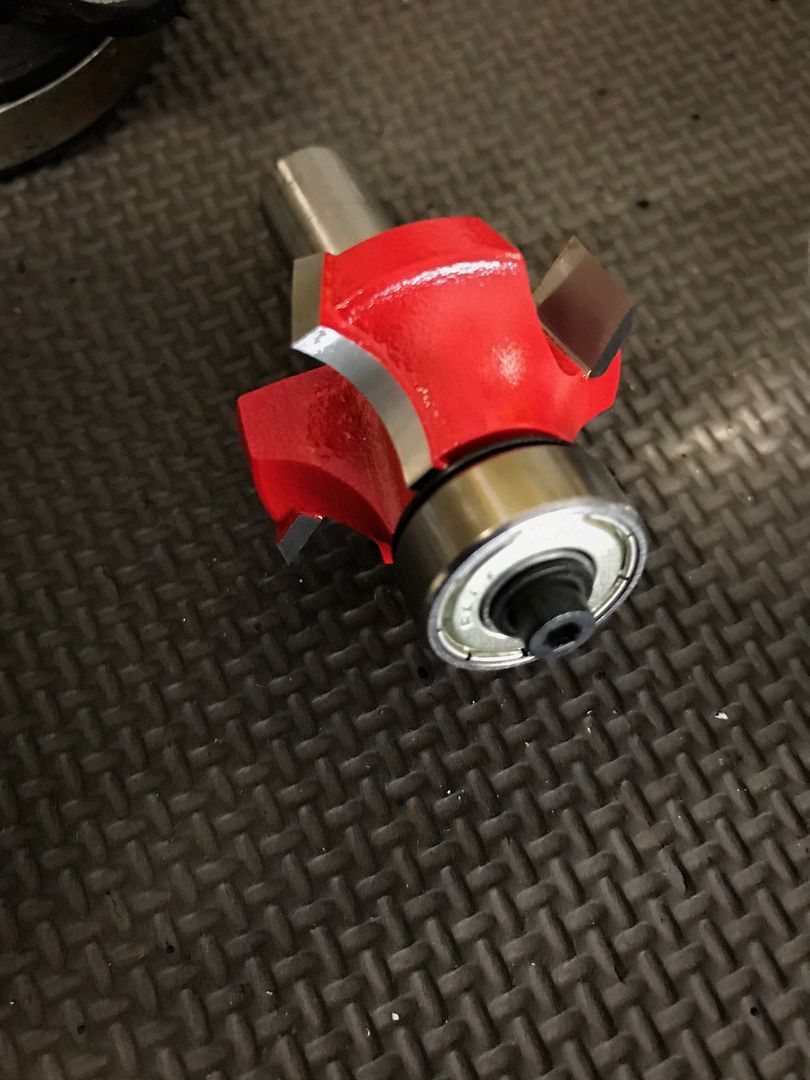  Huge mess but they turned out decent  Down the velocity stack  Once that chore was done, I assembled them for the last time with some RTV between the plate and the bottom of the rain hat. Then installed them on the car. 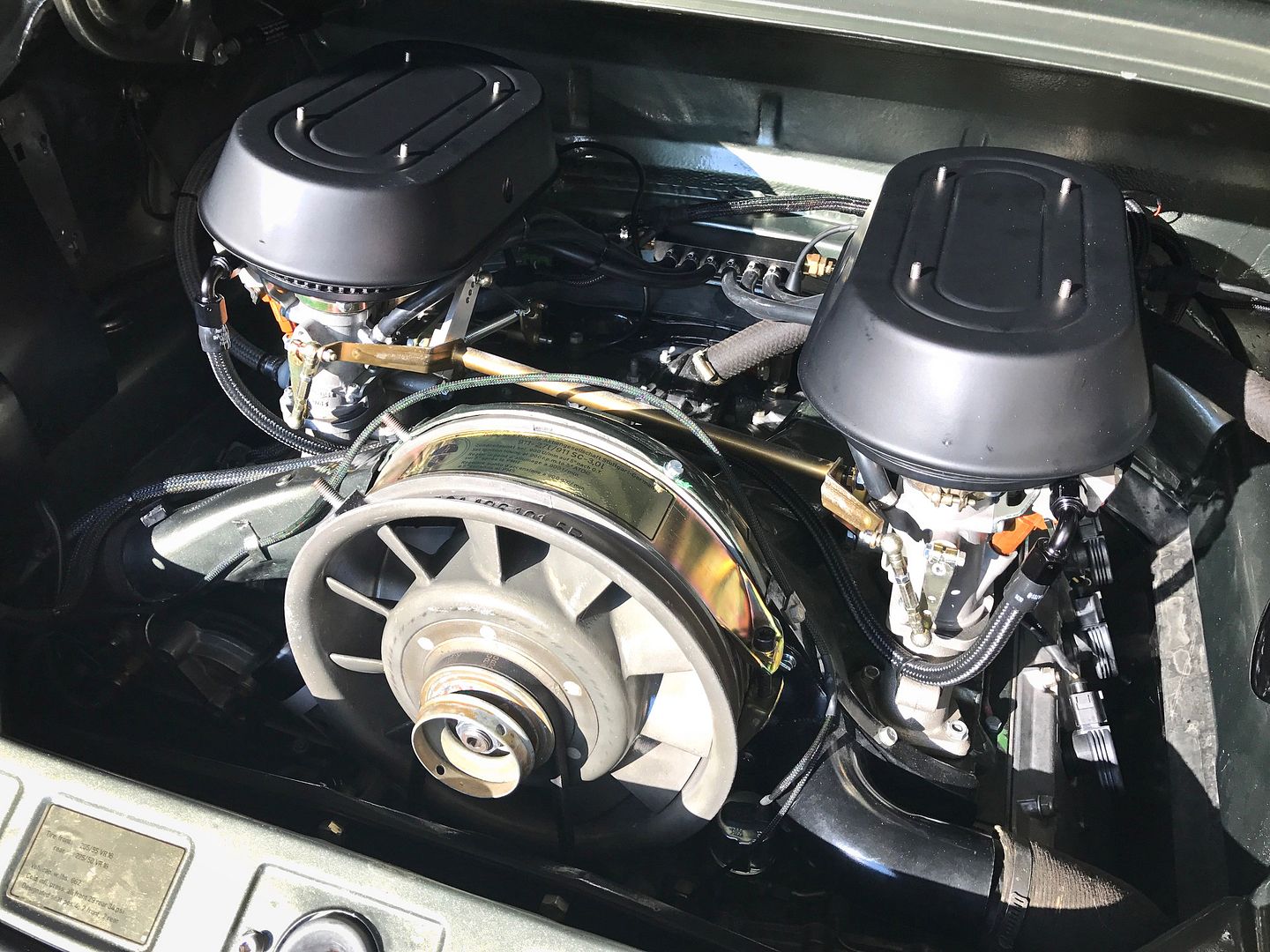 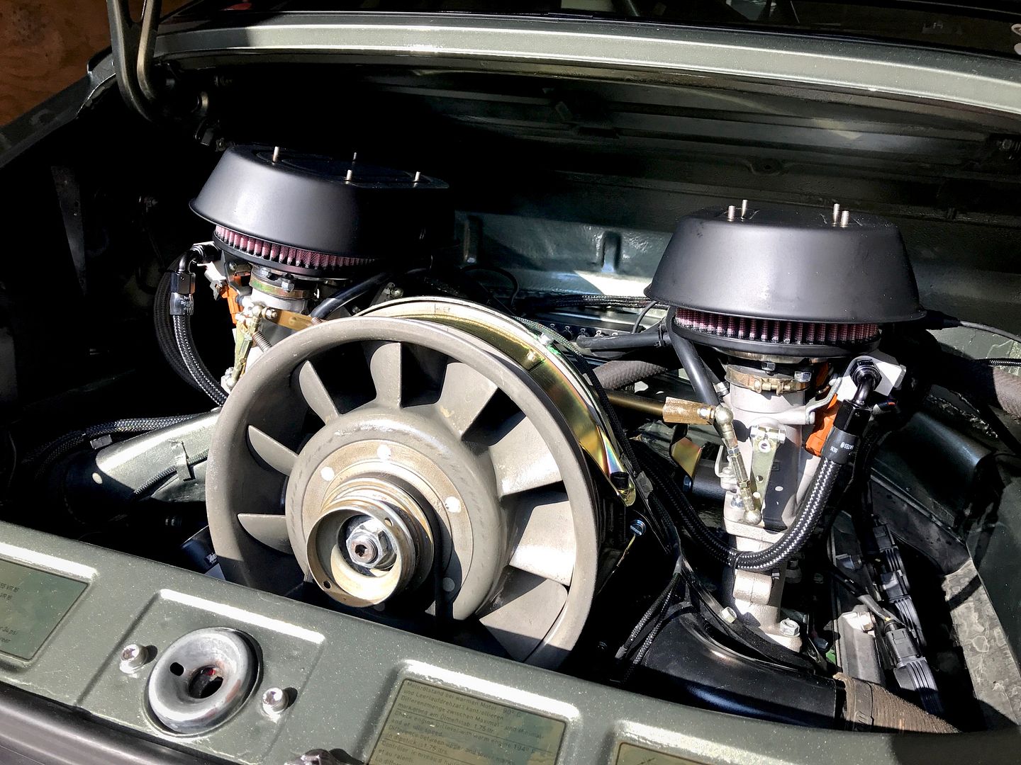 I still need to re-sync all the ITBs since I adjusted the linkage, then i'll install the top hat nuts. For now it's loose to protect the intakes. |
||
|
12-18-2016, 01:39 PM
|
|
|
Registered
Join Date: May 2005
Location: Houston
Posts: 5,488
|
You do some amazing work!
Inspiring.
__________________
Ole Skool - wouldn't have it any other way |
||
|
12-18-2016, 07:02 PM
|
|


 72 T
72 T 86 Carrera
 968CS
968CS Boxster S
 88 Carrera
 1971 Porsche 911S
